I am trying to understand what is reactive power. I have read that it has a relation with voltage, that is has a relation with the creation of a magnetic field in a motor, that it is coming and going between consumption and generators. But what exactly is the physical meaning of reactive power?
-
2$\begingroup$ Reactive power: the flow of traffic in rush hour such that, every time you change lanes, the net result is no forward motion -- regardless of how much effort you expended changing lanes! $\endgroup$– Cort AmmonCommented Oct 18, 2020 at 4:33
-
$\begingroup$ This is how we illustrate reactive power to new electrical engineers. $\endgroup$– MastCommented Oct 19, 2020 at 6:58
-
$\begingroup$ @Mast The beer is wrong, though; the image suggests S = P + Q, which is false; S = sqrt(P^2 + Q^2). Moreover, personally, using the beer analogy to introduce the concept of reactive power may be bad practice in the sense that it explains Q as a combination of P and S, but instead it is possible to talk about Q without mentioning P, S, or PF. $\endgroup$– alejnavabCommented Feb 17, 2021 at 1:47
-
$\begingroup$ @AlejandroNava People tend to know both P and beer from before starting the course, hence the approach. Like many analogies and illustrations, it's not exact. $\endgroup$– MastCommented Feb 17, 2021 at 16:20
6 Answers
But what exactly is the physical meaning of reactive power?
Essentially, reactive power is the component of power that has zero time average.
For example, consider a load consisting of a resistance $R$ in parallel with an inductance $L$ driven by a source with voltage $v_S(t) = V_S\cos \omega t$
Clearly, the source current is
$$i_S(t) = \frac{V_S}{R}\cos \omega t + \frac{V_S}{\omega L}\sin\omega t$$
Thus, the instantaneous power delivered by the source is
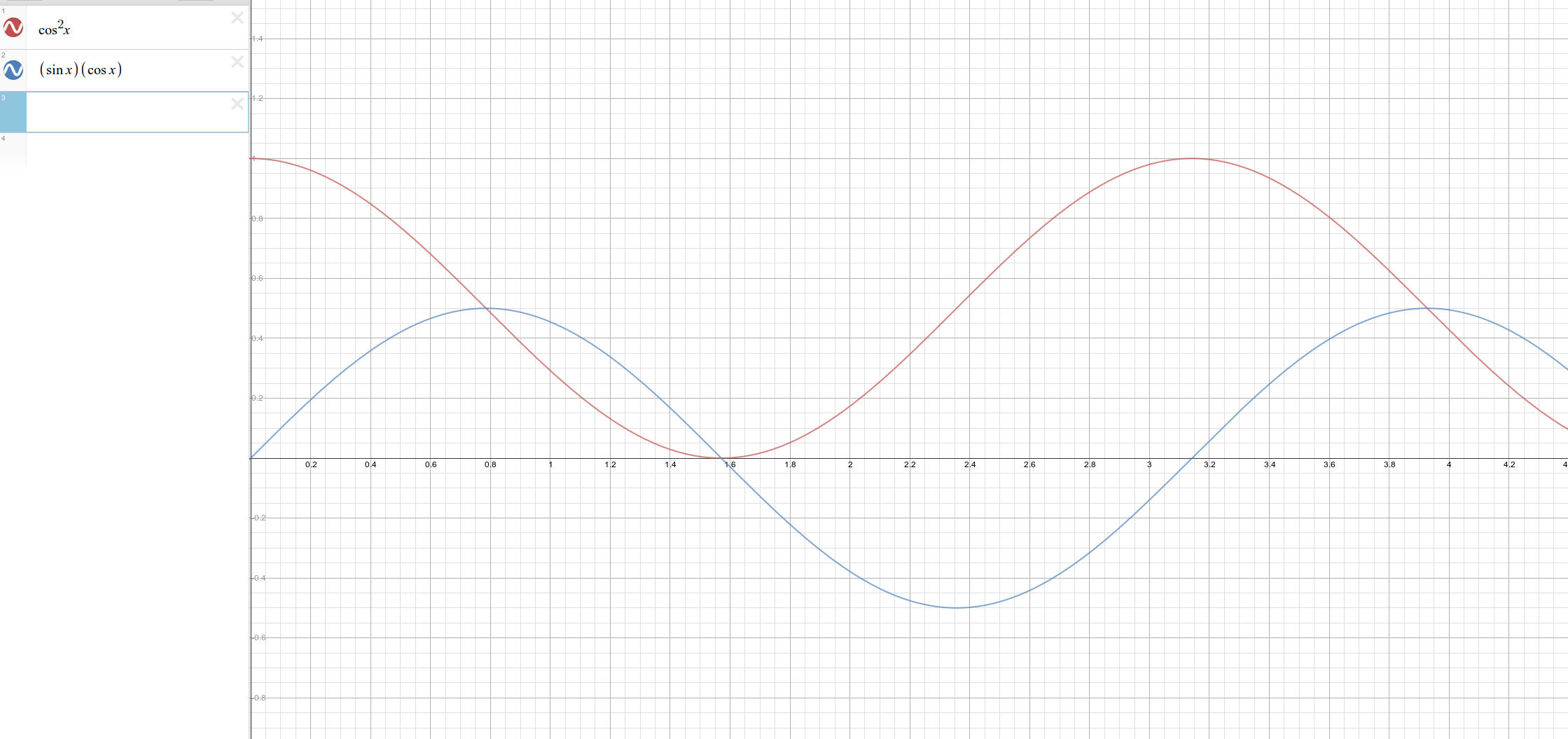
$$p_S(t) = v_S\cdot i_S = \frac{(V_S)^2}{R}\cos^2 \omega t + \frac{(V_S)^2}{\omega L}\sin \omega t\cos \omega t$$
Carefully note that the first term is never negative which is to say that the flow of energy described by this term is always from source to load or never from load to source.
However, the second term is positive over half of a cycle and negative the remaining half of a cycle. That is, this term describes energy that flows back and forth, in equal measure, between the source and load.
Take the time average of the power over a period:
$$\langle p_S\rangle = \frac{\omega}{\pi}\int_0^{\frac{\omega}{\pi}} p_S(\tau)\:\mathrm{d}\tau = \frac{1}{2}\frac{(V_S)^2}{R}$$
and see that only the first term has a non-zero time average; the second term does not contribute to the time average energy flow.
In the context of phasor analysis, the real power (the real part of the complex power) is equal to the time average of the instantaneous power.
The reactive power (the imaginary part of the complex power) is (proportional to) the amplitude of the second term in the instantaneous power.
And this is the physical meaning of reactive power; it is a measure of the energy flow back and forth between source and load.
-
$\begingroup$ Thank you for the effort and the time you dedicated for such an elaborate answer. I still don't understand how as an engineer i regulate the real part of power and frequency at the same time by increasing/decreasing fuel on a generator whereas i regulate voltage and the imaginary part of power by increasing/decreasing the field current of the rotor. This is the reason i posted a new question. Maybe the relation between voltage and reactive power sheds a new light to what is voltage. $\endgroup$– veronikaCommented Mar 12, 2016 at 17:39
-
$\begingroup$ @veronika - you regulate reactive power to motors using capacitors with the induction to get a power factor close to 1. $\endgroup$ Commented Oct 3, 2016 at 1:13
-
$\begingroup$ Correction when you said "Essentially, reactive power is the component of power that has zero time average": it's not reactive power whose average is zero, but instantaneous reactive power. $\endgroup$ Commented Oct 18, 2020 at 3:18
In sinusoidal steady-state (linear loads, no harmonics), the meaning of reactive power is known. In non-sinusoidal steady-state (non-linear loads, harmonics), I haven't read a textbook or article, or seen a video, or heard someone explain it; even literature doesn't have a unique definition of reactive power in these conditions, let alone its physical meaning. My answer, just like the others, will explain the meaning of reactive power in sinusoidal steady-state.
A the end of this answer I included equations you might not know. Throughout my answer I'll use the passive sign convention. This means that in the circuit diagram, we draw the reference direction of instantaneous current $i(t)$ and the reference polarity of instantaneous voltage $v(t)$, such that the current enters into the device by the positive reference terminal. When this convention is used, if the instantaneous power $p(t)$ is positive it means energy is flowing to the device (or load) from the external circuit (or source); if instantaneous power is negative it means energy is flowing from the device (or load) to the external circuit (or source.) The passive sign convention is commonly used for the loads.
1. Short answer
The absolute value of the reactive power of a device is the maximum/minimum rate of transfer of energy oscillating between the external circuit and the device. The net (not instantaneous) work done or the net energy transferred by the component of current that causes instantaneous reactive power, is zero joules.
2. Summary of concepts
The active component of current is the component of current that is in phase with the applied voltage, and corresponds to the active power. The reactive component of current is the component of current that is in quadrature (makes an angle of 90 degrees) with the applied voltage, and corresponds to the reactive power.
Instantaneous power is the rate of transfer of energy, or the rate of work being done; it can also be computed as the product of instantaneous voltage times instantaneous current. Instantaneous active power is that component of instantaneous power caused by the instantaneous active component of current. Instantaneous reactive power is that component of instantaneous power caused by the instantaneous reactive component of current. Active power is the average of the instantaneous power. Reactive power is the amplitude with sign of the instantaneous reactive power.
For example, if a load has an active power of +20 W (and voltage and current obey the passive sign convention), then it means that, on average, the load consumes 20 W each cycle of the instantaneous power. That is, the load on average consumes 20 joules of energy from the source each second in each cycle. If a load has a reactive power of +-13 VAR (the sign doesn't matter here), then it means that the highest rate at which energy oscillates between the source and load, is, in magnitude, 13 W or 13 joules per second. (Remember watts [W], volt-amperes [VA], volt-amperes reactive [VAR] and joules per second [J/s] are all dimensionally the same unit.)
3. Explanation (long answer)
In sinusoidal steady-state (which means all currents and all voltages have a sinusoidal waveform), any current can be decomposed into two parts: one component that is in phase with the voltage, and another component that is in quadrature with the voltage. The sum of these two components is equal to the current, whether using phasors or instantaneous values. If using phasors, "in-phase" means "parallel to", and "in quadrature" means "orthogonal (perpendicular) to." In the case of a three-phase load, “voltage” refers to phase voltage (the voltage across the load impedance) and “current” refers to phase current (the current through the load impedance.)
The in-phase component of current is also known as the active component of current, and the quadrature component is also known as the reactive component. By the end of this answer you’ll understand why these components are also called like that, but for now, just know those alternative names, which are more common in practice. Usually, instead of saying "active component of current" and "reactive component of current", people just say "active current" and "reactive current."
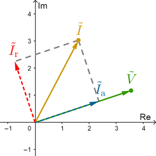
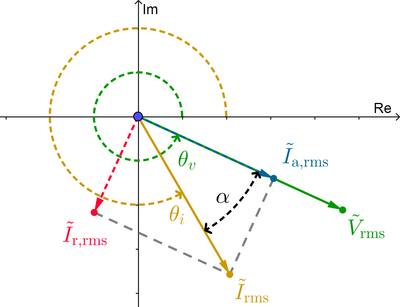
Here’s an example using phasors (complex numbers partially representing sinusoidal signals that electrical engineers use for analysis purposes):
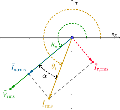
As you can see in the previous image, geometrically, the phasor active component (shown in blue) of the phasor current (shown in yellow) is the projection of the phasor current onto the phasor voltage (shown in green), and the phasor reactive component (shown in red) of the phasor current is orthogonal to the phasor active component. When the current is in phase with the voltage (as in ideal resistors), the reactive component is zero, and the active component is equal to the current. When the current is 90 degrees out of phase with the voltage (as in ideal inductors and capacitors), the active component is zero, and the reactive component is equal to the current. At any other angle, both components are present.
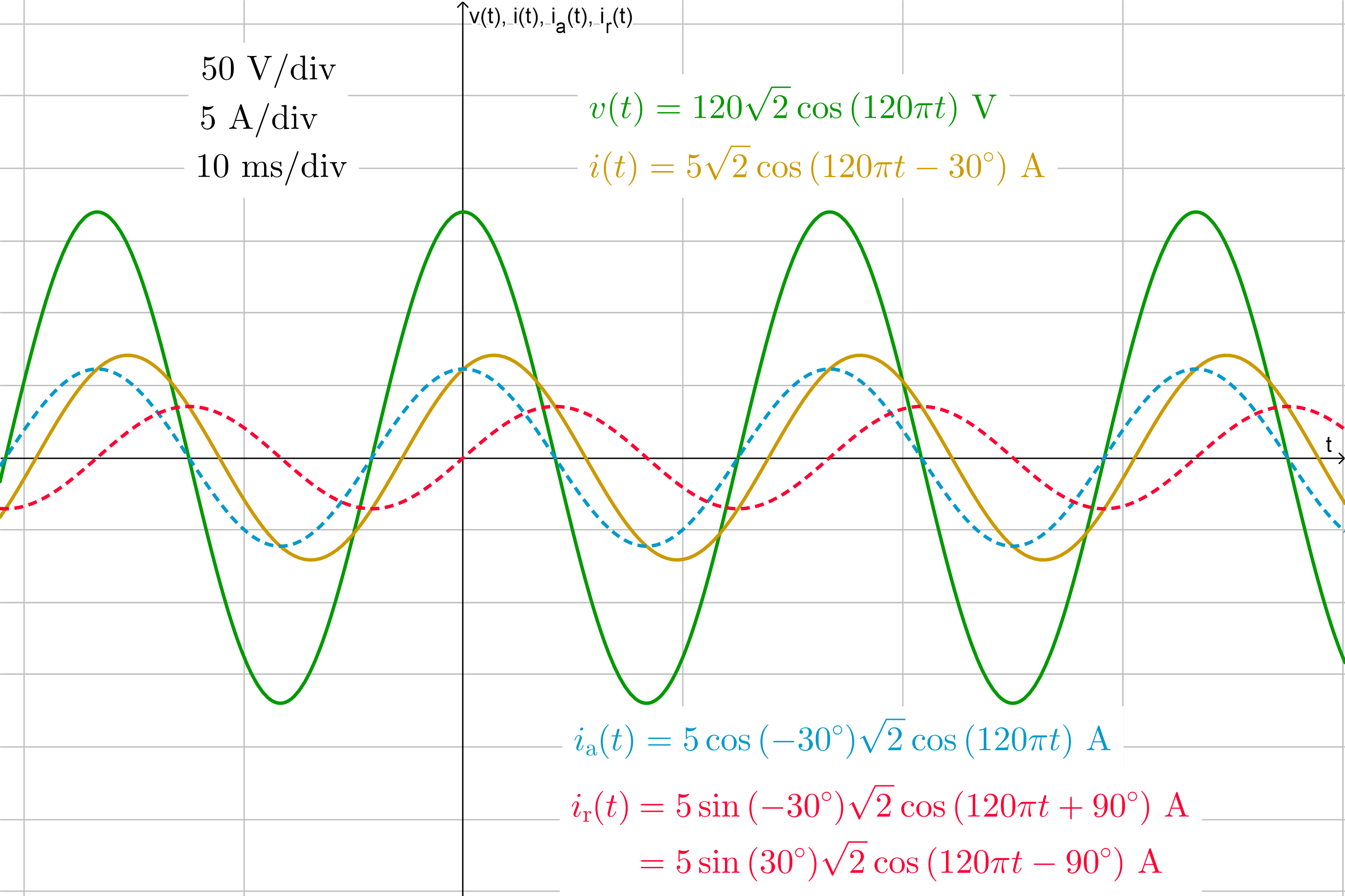
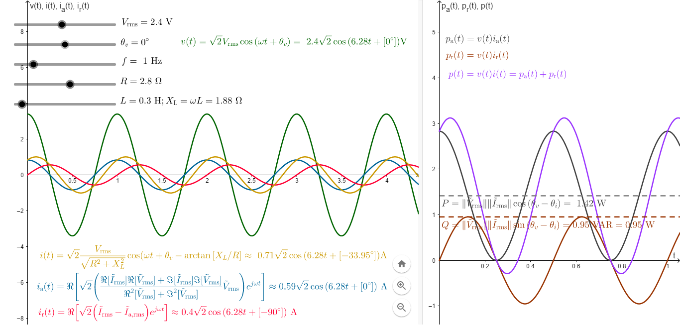
Here’s an example using instantaneous values (what you’d see using an oscilloscope):
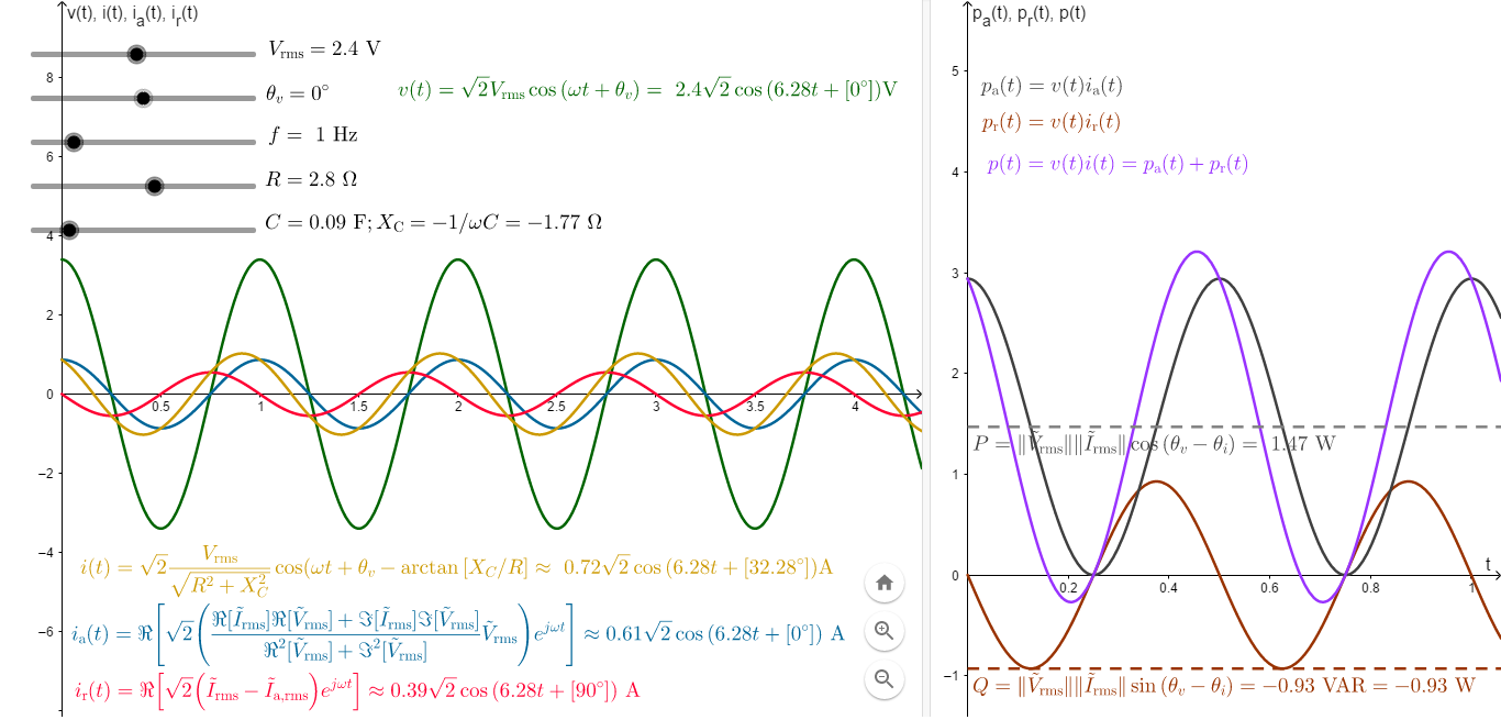
As you can see in the previous image, the instantaneous active component is in phase with the applied voltage, and the instantaneous reactive component lags or leads by 90°. This plus or minus 90° depends on whether the power factor is lagging (for RL loads) or leading (for RC loads), and the reason is as follows. In the case of an inductor, the current through it cannot change abruptly, but its voltage can; in a capacitor, the voltage across it cannot change abruptly, but its current can. The result is that in sinusoidal AC circuits in steady-state, in an inductor L the current I lags the voltage E, and in a capacitor C the current I leads the voltage E; this is where the phrase ELI the ICE man comes from.
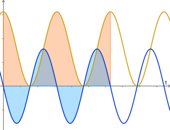
The instantaneous power absorbed by the load, which indicates the rate of transfer of energy to/from the load, is equal to the instantaneous voltage times the instantaneous current, but we can better understand it by expressing it in terms of the applied voltage and the active and reactive components of the resulting current. Here’s an example:
As you can see in the previous image,
- The power (shown in yellow) due to the active component of current results in energy (the area shown in orange) that never flows from load to source (because this component of power is always non-negative, using the passive sign convention.) In other words, energy either flows from source to load, or doesn't flow (when voltage or current are zero.) This is caused by the resistance of the load.
- The power (shown in dark blue) due to the reactive component of current results in energy (the area shown in light blue) that flows from source to load, is stored temporarily in the electromagnetic field, and is then released from load to source (because this component of power alternates between positive and negative values); it’s a lossless transfer of energy (although it causes $i^2 R$ losses, also known as copper losses, in the wires connecting the source and load.) This is caused by the inductance and capacitance of the load.
- The total instantaneous power (not shown) is the sum of these two curves.
In the previous image, you can see the average of the dark blue curve is zero, but the average of the yellow curve isn’t zero, which means the average of the instantaneous power, known as average power $P$, is just the average of the yellow curve. This implies the net energy transferred from source to load corresponds only to the yellow curve, because the dark blue curve has zero net energy. In fact, average power is also known as active power or real power (specially in power engineering) precisely because the net energy transferred from source to load corresponds to it. So, the yellow curve is known as the instantaneous active power $p_\text{a}(t)$. It can be proved that the net energy transferred or net work done in $n$ cycles of the instantaneous power is the active power $P$, times the number of cycles $n$ of the instantaneous power, times the period $T'$ of the instantaneous power: $W=P \cdot n \cdot T'$, where the period of $p$ is half the period of $v$ and $i$.
On the other hand, notice the dark blue curve contributes nothing to the average or active power (in other words, the dark blue curve doesn't contribute to the net energy transferred from source to load.) However, it still requires a fraction of the instantaneous current (which is the reactive component of current), so it’s important to consider it, because a greater current requires wires with higher diameter, for example. This power interacts or reacts with the electromagnetic field, so we call it the instantaneous reactive power $p_\text{r}(t)$, and its signed amplitude is the reactive power $Q$. Here, “signed amplitude” means “amplitude with sign”; this is important because in a RL load the amplitude is positive while in a RC load is negative, as you'll see below.
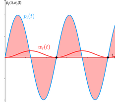
To better see how reactive current doesn't contribute to the net energy transferred, look at the following image. Instantaneous reactive power (the light blue curve) has a corresponding energy transferred due to the that component of power, which is the signed area under the curve, and which I'll call instantaneous reactive energy $w_\text{r}(t)$ (the red area, which is the same as the red curve.) In the following image, the net energy transferred by the reactive current is the value of the instantaneous reactive energy, where “net” means in $n$ complete cycles (at the end of $n$ full cycles.) This is the ordinate of each black point, which is zero as you can see. But at the remaining instants, the instantaneous energy is non-zero (look at the red curve), so instantaneous reactive power is very real; when it’s positive, energy is flowing from source to load through the wires; when it’s negative, energy is flowing from load to source through the wires. Nothing imaginary.
Since the amplitude of a sinusoidal signal means the maximum instantaneous value, the magnitude (absolute value) of the reactive power of a device is the maximum instantaneous power (maximum rate of transfer of energy) of that component of instantaneous current that does no net work (known as reactive current, which leads or lags the voltage by 90 degrees.)
Since the instantaneous active power (and the active power) is due to the in-phase component of current, we also call the latter as the active component of current. And since the instantaneous reactive power (and the reactive power) is due to the quadrature component of current, so we also call the latter as the reactive component of current.
What about the sign of reactive power? The following examples illustrate various of the previous concepts, along with the sign of reactive power (not to be confused with the sign of instantaneous reactive power, which alternates between positive and negative values regardless of the type of load.)
4. Two examples
I made two online interactive apps in GeoGebra, in which you can see the voltage, currents and powers waveforms. The following image is for a RL (inductive) load (modeled as a resistor in series with an inductor, most common type of loads in practice, for example motors). As an example, consider an inductive load with resistance of 2.8 ohms and inductive reactance of 1.88 ohms. Suppose we apply 2.4 V rms across it, and we choose this voltage as angular reference (this means its phase angle will be 0 degrees using the cosine function.) Then the reactive power will be $Q=+0.95 \text{ VAR}$.
Notice in that case, reactive power is positive. What does this mean?! It means that the maximum rate of transfer of energy by the quadrature (or reactive) component of current, is 0.95 watts or 0.95 joules per second. That is, at the instants when $p_\text{r}(t)=Q>0$, the energy due to this component of power is flowing from source to load and its rate of transfer is maximum.
The following image is for a RC (capacitive) load (modeled as a resistor in series with a capacitor). Now consider another, capacitive load, with a resistance of 2.8 ohms and capacitive reactance of -1.77 ohms. Once again suppose we apply 2.4 V rms across it. The reactive power is $Q=-0.93 \text{ VAR}$.
Notice in that case, reactive power is negative. This means that the minimum rate of transfer of energy by the quadrature component of current, is 0.93 joules each second. That is, at the instants when $p_\text{r}(t) = Q < 0$, the energy due to this component of power is flowing from load to source and its rate of transfer is minimum (maximum in absolute value.)
As you can see, there’s nothing imaginary about reactive power. Some people might have thought reactive power was imaginary, because in the complex power expression, $S = P + jQ$, it looks like it is imaginary. But what is imaginary is the number $jQ$, not $Q$. Remember any imaginary number is of the form $jb$, where $b$ is a real number!
I hope this helps in understanding what is reactive power, and just as important, why.
5. Relevant equations
In this section I'll show the equations for active and reactive components of current (both instantaneous and phasor), and, instantaneous active and instantaneous reactive power. I haven't read a textbook in which they show these, so that's why I'm sharing them.
The (real) instantaneous voltage and the (real) instantaneous current, in sinusoidal steady-state, are:
$v(t)=V_\text{max} \cos{(\omega t+\theta_v)} \tag*{}$
$i(t)=I_\text{max} \cos{(\omega t+\theta_i)} \tag*{}$
The phasors corresponding to the previous sinusoidal signals are:
$\tilde{V}=V_\text{max} \, e^{j \theta_v} \tag*{}$
$\tilde{I}=I_\text{max} \, e^{j \theta_i} \tag*{}$
Notice I’ll denote phasors with a tilde on top (~), while amplitudes (either peak values or RMS values) without a tilde, for example $\| \tilde{I} \| = I_\text{max}$. The relationship between the real instantaneous values and the phasors are:
$v(t)=\Re[\tilde{V}e^{j \omega t}] \tag*{}$
$i(t)=\Re[\tilde{I}e^{j \omega t}] \tag*{}$
Using instantaneous values, the current can be decomposed into its instantaneous active and reactive components:
$i(t)= i_{\text{a}}(t)+i_{\text{r}}(t) \tag*{}$
or using phasors, the current can be decomposed into its phasor active and reactive components (which is valid because both components have the same frequency and is equal to the frequency of the total current $i$):
$\tilde{I}=\tilde{I}_{\text{a}}+\tilde{I}_{\text{r}} \tag*{}$
The phasor active and reactive components can be computed as:
$\begin{align} \tilde{I}_{\text{a}} &= \text{proj}_{\tilde{V}}(\tilde{I}) \tag 1 \\ &= \left( \dfrac{\tilde{I} \cdot \tilde{V}}{\| \tilde{V} \|^2} \right) \tilde{V} \tag 1 \\ &= \left( \dfrac{\Re[\tilde{I}] \Re[\tilde{V}] + \Im[\tilde{I}] \Im[\tilde{V}]}{\Re[\tilde{V}]^2 + \Im[\tilde{V}]^2} \right) \tilde{V} \tag 2 \end{align}$
$\begin{align} \tilde{I}_{\text{r}} &= \tilde{I}-\tilde{I}_{\text{a}} \\ &= (\Re[\tilde{I}]-\Re[\tilde{I}_{\text{a}}])+j(\Im[\tilde{I}] - \Im[\tilde{I}_{\text{a}}]) \end{align} \tag 3$
where $\text{proj}_{\tilde{V}}(\tilde{I})$ is the “projection” of current phasor onto the voltage phasor, and $\tilde{I} \cdot \tilde{V}$ is the “dot product” of the phasors $\tilde{I}$ and $\tilde{V}$. As far as I know, technically there’s no such thing as the projection of a complex number onto another or the dot product of two complex numbers, but I’m borrowing this terminology from vector analysis. So, if you want you can ignore equation (1), but equation (2) is correct in all senses.
As I said, I haven't seen a textbook in electrical engineering that shows how to compute $\tilde{I}_{\text{a}}$ and $\tilde{I}_{\text{r}}$, so how do I know the equations (2) and (3)? From section 11.3 of the textbook Multivariable Calculus, vol. II (9th edition) by Ron Larson and Bruce Edwards, in which they use bidimensional real vectors instead of complex numbers. The only thing I did was adapt the equations of vector analysis into complex analysis.
Since we can decompose instantaneous current into its active and reactive components, we can also decompose instantaneous power:
$p(t)=v(t) \, i(t)=v(t) \, i_{\text{a}}(t)+v(t) \, i_{\text{r}}(t) \tag*{}$
where the first term is defined as the instantaneous active power $p_{\text{a}}(t)$, and the second term as instantaneous reactive power $p_{\text{r}}(t)$. These names are used in section 2.9 of the textbook Circuitos eléctricos [in Spanish] by Jesús Fraile Mora, although I'm using different equations than his, but both are equivalent.
In power engineering, it’s common to work with RMS values instead of peak values; in such cases, we can express the following relations:
$\tilde{V}_\text{rms} = \dfrac{\tilde{V}}{\sqrt{2}} \implies \| \tilde{V}_\text{rms} \| = \dfrac{\| \tilde{V} \|}{\sqrt{2}} \implies v(t)=\Re[\sqrt{2} \, \tilde{V}_\text{rms} \, e^{j \omega t}]; \tag*{}$
$\tilde{I}_\text{rms}=\dfrac{\tilde{I}}{\sqrt{2}} \implies \| \tilde{I}_\text{rms} \|=\dfrac{\| \tilde{I} \|}{\sqrt{2}} \implies i(t)=\Re[\sqrt{2} \tilde{I}_\text{rms} \, e^{j \omega t}]; \tag*{}$
$\tilde{I}_{\text{a,rms}}=\dfrac{\tilde{I}_{\text{a}}}{\sqrt{2}} \implies \| \tilde{I}_{\text{a,rms}} \|=\dfrac{\| \tilde{I}_{\text{a}} \|}{\sqrt{2}} \implies i_{\text{a}}(t)=\Re[\sqrt{2} \, \tilde{I}_{\text{a,rms}} \, e^{j \omega t}]; \tag*{}$
$\tilde{I}_{\text{r,rms}}=\dfrac{\tilde{I}_{\text{r}}}{\sqrt{2}} \implies \| \tilde{I}_{\text{r,rms}} \|=\dfrac{\| \tilde{I}_{\text{r}} \|}{\sqrt{2}} \implies i_{\text{r}}(t)=\Re[\sqrt{2} \, \tilde{I}_{\text{r,rms}} \, e^{j \omega t}]; \tag*{}$
It’s also common to choose the voltage as angular reference (this means that $\theta_v = 0°$.) Using RMS values and taking the voltage as angular reference, the general expressions for the phasor active and reactive components of current reduce to the following:
$\begin{align} \tilde{I}_{\text{a,rms}} &= \Re[\tilde{I}_\text{rms}] \\ &= \| \tilde{I}_\text{rms} \| \cos{(\theta_i)} \\ &= \| \tilde{I}_\text{rms} \| \cos{(\theta)} \end{align} \tag*{}$
$\begin{align} \tilde{I}_{\text{r,rms}} &= j\, \Im[\tilde{I}_\text{rms}] \\ &= j \| \tilde{I}_\text{rms} \| \sin{(\theta_i)} \\ &= -j \| \tilde{I}_\text{rms} \| \sin{(\theta)} \end{align} \tag*{}$
where $\theta$ is the power factor angle, defined in general as $\theta = \theta_v - \theta_i$. These expressions are valid only when $\theta_v = 0°$.
6. Active and reactive power in terms of active and reactive current
The active and reactive power in terms of the RMS active and reactive components of current are:
$P=\| \tilde{V}_\text{rms} \| \| \tilde{I}_\text{a,rms} \| \tag 4$
$|Q|=\| \tilde{V}_\text{rms} \| \| \tilde{I}_\text{r,rms} \| \tag 5$
But how do I prove this?
6.1. Proving equation (4)
Let's first prove equation (4). As you should know from circuit analysis or power systems analysis, it can be proved that the average power of the instantaneous power is
$P = \| \tilde{V}_\text{rms} \| \| \tilde{I}_\text{rms} \| \cos{(\theta_v - \theta_i)} \tag 6$
So, if it is indeed true that $P$ can also be computed with equation (6), it means (4) and (6) can be equated:
$\| \tilde{V}_\text{rms} \| \| \tilde{I}_\text{rms} \| \cos{(\theta_v - \theta_i)} \overset{?}{=} \| \tilde{V}_\text{rms} \| \| \tilde{I}_\text{a,rms} \| \implies \| \tilde{I}_\text{rms} \| \cos{(\theta)} \overset{?}{=} \| \tilde{I}_\text{a,rms} \| \tag 7$
Thus I only have to prove that the left-hand side of (7) is equal to the right-hand side. I'll use geometry and vector analysis for this demonstration. I'll prove this for a RL load and a RC load.
6.1.1. Proving equation (7) for a RL load
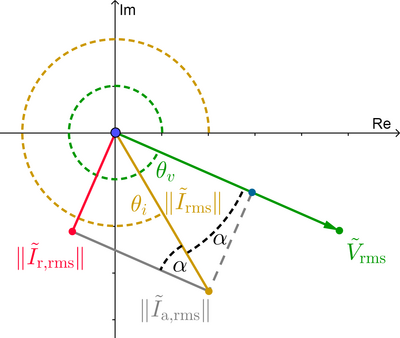
In the case of a RL load, phasor current lags phasor voltage by an angle between zero and +90°: $0 < \theta_v - \theta_i = \theta < 90°$. The angles $\theta_v$ and $\theta_i$ are the angles of the phasor voltage and current, measured from the real positive semiaxis in counterclockwise direction, which results in angles between 0° and 360° (in electrical engineering it's common to use angles between -180° and +180°, but you can express a negative angles as a positive angle by summing 360°, which is valid because the sine and cosine functions are periodic.) The following image illustrates the scenario.
Between two complex numbers (or two vectors) there're two angles; in the previous image, $\alpha$ will be the smallest angle between $\tilde{V}_\text{rms}$ and $\tilde{I}_\text{rms}$. In a RL load, $\alpha=\theta=\theta_v-\theta_i$.
Remember that the dot product of two vectors, or complex numbers in our case, can be computed in two ways: as the sum of the product of their respective components (as in equation (1.2)), or, as the product of their magnitudes times the cosine of the smallest angle between them. The relevant form is the latter, so:
$\tilde{V}_\text{rms} \cdot \tilde{I}_\text{rms}=\| \tilde{V}_\text{rms} \| \| \tilde{I}_\text{rms} \| \cos{(\alpha)} \tag*{}$
Substituting this "dot product" in equation (1), and writing the phasor voltage in exponential form $\tilde{V}_\text{rms} = \| \tilde{V}_\text{rms} \| \, e^{j \theta_v}$, and using RMS phasors, we have:
$\tilde{I}_{\text{a,rms}}=\left( \dfrac{\| \tilde{V}_\text{rms} \| \| \tilde{I}_\text{rms} \| \cos{(\alpha)}}{\| \tilde{V}_{\text{rms}} \|^2} \right) (\| \tilde{V}_\text{rms} \| \, e^{j \theta_v})=\| \tilde{I}_\text{rms} \| \cos{(\alpha)} \, e^{j \theta_v} \tag*{}$
Thus, the magnitude of $\tilde{I}_{\text{a,rms}}$ is obtained by dropping the factor $e^{j \theta_v}$ (since this just changes the angle); we don't have to worry about the sign of the cosine function because the cosine of an angle between 0° and 90° is positive. Also, since this is a RL load, $\alpha = \theta_v - \theta_i = \theta$. Therefore:
$\| \tilde{I}_{\text{a,rms}} \|=\| \tilde{I}_\text{rms} \| \cos{(\theta)} \tag*{}$
which is equation (7)!
6.1.2. Proving equation (7) for a RC load
In the case of a RC load, phasor current leads phasor voltage by an angle between zero and +90°: $-90°< \theta_v-\theta_i = \theta <0°$. In a RC load, $\alpha=-\theta=\theta_i-\theta_v$. The phasor diagram is now:
You proceed the same as before, but now you get:
$\tilde{I}_{\text{a,rms}}=\| \tilde{I}_\text{rms} \| \cos{(\alpha)} \, e^{j \theta_v}=\| \tilde{I}_\text{rms} \| \cos{(-\theta)} \, e^{j \theta_v} \tag*{}$
but since the cosine is an even function, and the cosine of an angle between -90° and 0° is positive:
$\| \tilde{I}_{\text{a,rms}} \| = \| \tilde{I}_\text{rms} \| \cos{(\theta)} \tag*{}$
which is equation (7). Therefore, equation (4) is valid for any type of load.
6.2. Proving equation (5)
In regards to (5), reactive power is defined as:
$\begin{align} Q &= \| \tilde{V}_\text{rms} \| \| \tilde{I}_\text{rms} \| \sin{(\theta_v-\theta_i)} \\ \implies |Q| &= \| \tilde{V}_\text{rms} \| \| \tilde{I}_\text{rms} \| |\sin{(\theta_v - \theta_i)}| \\ &= \| \tilde{V}_\text{rms} \| \| \tilde{I}_\text{rms} \| \sin{|\theta_v-\theta_i|} \tag 8 \end{align}$
If it's true that $Q$ can also be computed with equation (8), it means (5) and (8) can be equated:
$\| \tilde{V}_\text{rms} \| \| \tilde{I}_\text{rms} \| \sin{|\theta_v - \theta_i|} \overset{?}{=} \| \tilde{V}_\text{rms} \| \| \tilde{I}_\text{r,rms} \| \implies \| \tilde{I}_\text{rms} \| \sin{|\theta|} \overset{?}{=} \| \tilde{I}_\text{r,rms} \| \tag 9$
Once again, I have to prove that (9) is a valid relation.
6.2.1. Proving equation (9) for a RL load
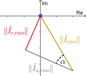
Let's go back to the phasor diagram used to prove (4) for the RL load, and draw a right triangle as follows:
or more clearly:
Using the basic trigonometry (definition of the sine function):
$\sin{(\alpha)}=\dfrac{\| \tilde{I}_\text{r,rms} \|}{\| \tilde{I}_\text{rms} \|} \implies \| \tilde{I}_\text{r,rms} \|=\| \tilde{I}_\text{rms} \| \sin{(\alpha)}=\| \tilde{I}_\text{rms} \| \sin{(\theta)} \tag*{}$
which is almost equation (9)! We don't have to worry about the sign of the sine function because the sine of an angle between 0° and +90° is positive.
6.2.2. Proving equation (9) for a RC load
Following the same steps, you get: $\| \tilde{I}_\text{r,rms} \| = \| \tilde{I}_\text{rms} \| \sin{(\alpha)}$. In this case, $\alpha = -\theta$, and $\theta$ is between -90° and 0°, so $-\theta$ is positive, and the sine of an angle between 0° and + 90° is positive. So this equation is also correct regarding the sign. This is almost equation (9).
In the case of RL load we used $\theta > 0$ and in the case of the RC load we used $-\theta > 0$. The only thing that matter is the magnitude (absolute value) of the difference $\theta_v - \theta_i$. So we can say that whether for a RL or RC load:
$\| \tilde{I}_\text{r,rms} \| = \| \tilde{I}_\text{rms} \| \sin{|\theta|} \tag*{}$
and this is exactly the same as (9). Therefore, equation (5) is valid for any type of load.
7. Proving the absolute value of reactive power is the amplitude of instantaneous reactive power
In my short and long answers, I said the absolute value of reactive power was the amplitude of instantaneous reactive power. But I didn't prove it, I just showed two examples. More specifically, how can I prove that the absolute value of $Q = \| \tilde{V}_\text{rms} \| \| \tilde{I}_\text{rms} \| \sin{(\theta)}$ is the amplitude of $p_\text{r}(t)$?
Instantaneous reactive power, as I said earlier, was the product of instantaneous voltage and the instantaneous reactive component of current: $p_\text{r}(t) = v(t) \, i_\text{r}(t)$. Obviously, $v(t)$ and $i_\text{r}(t)$ have some amplitude and some phase shift; they have the general form: $v(t)= sqrt{2} \| \tilde{V}_\text{rms} \| \cos{(\omega t+ \theta_v)}$ and $i_\text{r}(t)=\sqrt{2} \| \tilde{I}_\text{r,rms} \| \cos{(\omega t+ \theta_{i_\text{r}})}$.
However, as we saw earlier, $\| \tilde{I}_\text{r,rms} \| = \| \tilde{I}_\text{rms} \| \sin{|\theta|}$. Also, since $i_\text{r}(t)$ is by definition in quadrature with $v(t)$, we can say that $\theta_{i_\text{r}} = \theta_v \mp 90°$, where you use the first/upper sign if the load is RL or the second/lower sign if it's RC. Substituting these expression in $i_\text{r}$, we get: $i_\text{r}(t) = \sqrt{2} \| \tilde{I}_\text{rms} \| \sin{|\theta|} \cos{(\omega t + \theta_v \mp 90°)}$.
Substituting the expressions for $v$ and $i_\text{r}$ into $p_\text{r}$ yields:
$\begin{align} p_\text{r}(t) &= [\sqrt{2} \| \tilde{V}_\text{rms} \| \cos{(\omega t+ \theta_v)}] \, [\sqrt{2} \| \tilde{I}_\text{rms} \| \sin{|\theta|} \cos{(\omega t+ \theta_v \mp 90°)}] \\ &= 2 \underbrace{\| \tilde{V}_\text{rms} \| \| \tilde{I}_\text{rms} \| \sin{|\theta|}}_{=|Q|} \cos{(\omega t+ \theta_v)} \cos{(\omega t+ \theta_v \mp 90°)} \\ &= 2|Q| \cos{(\omega t+ \theta_v)} \cos{(\omega t+ \theta_v \mp 90°)} \end{align} \tag*{}$
Now we apply the trigonometric identity $\cos{(x)} \cos{(y)} = [\cos{(x-y)} + \cos{(x+y)}]/2$:
$\begin{align} p_\text{r}(t) &= 2|Q| \left[ \dfrac{\cos{([\omega t+ \theta_v] - [\omega t+\theta _v \mp 90°])}+\cos{([\omega t+ \theta_v]+[\omega t+ \theta _v \mp 90°])}}{2} \right] \\ &= |Q|[\underbrace{\cos{(\pm 90°)}}_{=0}+\cos{(2 \omega t + 2 \theta_v \mp 90°)}] \\ &= |Q| \cos{(2 \omega t+2 \theta_v \mp 90°)} \end{align} \tag*{}$
from which is clear the amplitude of $p_\text{r}$ is $|Q|$, QED. So, indeed the absolute value of reactive power is the maximum/minimum rate of transfer of the energy flowing between source and load.
As a side note, if we proceed similarly for instantaneous active power, and remember that $\| \tilde{I}_\text{a,rms}\|=\| \tilde{I}_\text{rms}\| \cos{(\theta)}$ and $\theta_{i_\text{r}} = \theta_v$, and use the identity $\cos^2{(x)}=[1+\cos{(2x)}]/2$, then we get:
$p_\text{a}(t)=P[1+\cos{(2\omega t+2\theta_v)}]\tag*{}$
using the passive sign convention.
-
$\begingroup$ In summary, in sinusoidal steady-state, the magnitude (or absolute value) of the reactive power of a two-terminal load/network/device is the maximum rate of transfer of the energy oscillating between the load/network under consideration and the external source/network. (By the way, "maximum rate of transfer of oscillating energy" is a synonym of "amplitude of the instantaneous reactive power".) Well, turns out IEEE standard 1459-2010 agrees with my conclusion; they say on 4: "The magnitude of the reactive power $Q$ equals the amplitude of the oscillating instantaneous reactive power $p_q$". $\endgroup$ Commented Apr 5, 2021 at 22:20
-
$\begingroup$ Complex numbers are an algebra: a vector space with a multiplication. For complex numbers, the vector space is the set of two element vectors over the real numbers. So it’s totally ok to talk about the projection of one complex number onto another. $\endgroup$– NicNic8Commented Jan 10 at 3:53
It means that the current an voltage are not exactly in phase with one another as they would be for a resistor.
If the phase difference between the voltage and the current is $\delta$ then the power dissipated is in a component is $V_{\text{rms}} I_{\text{rms}} \cos \delta$. This is called the read or active power and is measured in watts.
The reactive power is $V_{\text{rms}} I_{\text{rms}} \sin\delta$ and it is measured in volt-ampere reactive or var.
It is the maximum power absorbed or given out by reactive circuit elements.
So for your motor the coil would have inductance and resistance (and possibly capacitance).
The resistive part would dissipate energy as heat whereas the reactive part would store and then give back energy.
If $\delta = 90^\circ$ then the current and voltage are such that every quarter of a cycle the reactive component is absorbing power (the magnetic field in an inductor is increasing or the electric field in a capacitor is increasing) and then for the next quarter cycle the the reactive component is giving out energy (magnetic/electric field decreasing).
-
$\begingroup$ Thank you very much for your answer. But i still don't understand the google explanations. Why is reactive power related to voltage? How it "returns" to the source when a magnetic field decreases? $\endgroup$– veronikaCommented Mar 10, 2016 at 19:13
I'm an electrical engineer also at odds with how has reactive power being described or rather thought about, and this is because utilities don't like it. This is because reactive power brings losses to transmission lines, but you know what? It's innevitable, because of two reasons:
To correct one of your concepts, reactive power (KVAR) is a natural component of electrical power (KVA), not of voltage. The simplest way I put it is: KVA = KW + KVAR And then is a matter of how much of each, which brings the other point.
Many loads need it, in fact every magnetic load will use it. So, unless there are devices that supply reactive power at the load, the utility generators provide it...naturally. Along with whatever undesirable effects.
-
$\begingroup$ Reactive power is not inevitable, it can easily be eliminated from motor circuits using capacitors. Every electrical engineer or even competent electrician should know that. $\endgroup$ Commented Oct 3, 2016 at 1:09
-
$\begingroup$ This part of my answer - unless there are devices that supply reactive power at the load - goes along with your comment, Ms. Hirose. The reactive component is not being "eliminated", it's supplied by the capacitors. $\endgroup$ Commented Oct 3, 2016 at 13:16
-
$\begingroup$ S is not P + Q, it's sqrt(P^2 + Q^2). That's as wrong as the beer analogy many prople use. $\endgroup$ Commented Oct 17, 2020 at 1:10
Another relative term..."work", which for electricity usually means some measure of heat. Saying that reactive power doesn't perform real work, seems to be incorrect. Of course, for an iron heating element, the reactive component is nearly zero (it's there, just contributes almost nothing), but the fan...it needs this reactive component, and so...it's doing something.
Magnetic systems, as in...a maglev train system is pushing up and forward tons of weight...at very high speeds; isn't that work? Maybe there's not much heat (well, transformers and cables will get hot), but there is certainly a big force.
I think it's important to understand that some concepts were influenced by whatever knowledge was at the time; new knowledge should modify them. "Work" means something is moving, something is being done, which uses energy or power. It's not just the real (watts) component or the imaginary (reactive) component, they're both contained in the electrical energy form, and the nature of the load determines how much of each component will be used.
Reactive power is basically the pulsating power whose time average for a complete cycle is zero. This power does not perform any real work. Here real work means that heater will not produce heat using this power or fan will not rotate merely by reactive power. For physical significance, just take the example of a coolie carrying your language. In terms of physics he is not performing any work but still we pay them. The same analogy can be applied for reactive power. If voltage and current are in quadrature as is the case with pure inductor / capacitor, the real power consumed will be zero. But in case of pure resistance, as the current is along the voltage, it will consume real power and hence heating effect will be produced.
Source: Active, Reactive and Apparent Power - Electrical Concepts
-
$\begingroup$ I suppose you actually mean "luggage" in "coolie carrying your language." It also appears that coolie is a rather pejorative/derogatory, you may want to consider changing it to something less demeaning. $\endgroup$ Commented May 10, 2018 at 10:01
-
1$\begingroup$ Correction when you said "This power does not perform any real work": At each instant, yes, it does work. On average, it doesn't; that is, the net work done is zero. $\endgroup$ Commented Oct 18, 2020 at 4:02

