My initial intuition after watching this video was that Derek's claim was technically true but only for an uninteresting reason. Namely, he stated that the lamp will light up once any current at all flows through it. Well, of course an infinitely sensitive amperemeter will react to the flip of the switch with the speed of light! (It will probably react to your neurons firing just thinking about it as well.) But given a realistic lamp and a realistic battery, wouldn't the immediate current be many orders of magnitude weaker that the operating current?
Turns out my intuition was wrong, so I'd like to give a quantitative answer to this question.
The circuit consists of two stretches of transmission line connected to each other through the lamp and the battery. Each stretch is shorted at the opposite end from the lamp. The change of voltage and current within the lines is described by the telegrapher's equations, with the lamp, battery and shorted ends defining the boundary conditions.
Here is an equivalent circuit where capacitors and inductors represent capacitance and inductance of an infinitesimal fragment of a transmission line:
- $V_{R} (t,x)$ is the potential difference between the top and the bottom wires at distance $x$ to the right of center at the moment $t$
- $V_{L} (t,-x)$ is the potential difference between the top and the bottom wires at distance $x$ to the left of center at the moment $t$
- $I_{R} (t,x)$ is the current at distance $x$ to the right of center at the moment $t$
- $I_{L} (t,-x)$ is the current at distance $x$ to the left of center at the moment $t$
- $L'$ is the transmission line inductance per unit length
- $С'$ is the transmission line capacitance per unit length
- $\mathcal{E}$ is the electromotive force of the battery
- $R$ is the resistance of the lamp
Let's calculate the current $I(t,0)$ flowing through the lamp, and how the immediate current at $t=0$ relates to the operating current $I_{lim}=\frac{\mathcal{E}}{R}$.
Applying the lossless general solution of the telegrapher's equations to each of the two stretches of transmission line:
$$ \begin{array}{ l l r } V_{R} (t,x)&=v_{R}^{+}\left( t-\frac{x}{u}\right) +v_{R}^{-}\left( t+\frac{x}{u}\right) & \qquad\textrm{(A1)}\\[0.3em] I_{R} (t,x)&=\frac{1}{Z_{0}}\left( v_{R}^{+}\left( t-\frac{x}{u}\right) -v_{R}^{-}\left( t+\frac{x}{u}\right)\right) & \qquad\textrm{(A2)} \\[0.3em] V_{L} (t,-x)&=-v_{L}^{+}\left( t-\frac{x}{u}\right) -v_{L}^{-}\left( t+\frac{x}{u}\right) & \qquad\textrm{(A3)}\\[0.3em] I_{L} (t,-x)&=\frac{1}{Z_{0}}\left( v_{L}^{+}\left( t-\frac{x}{u}\right) -v_{L}^{-}\left( t+\frac{x}{u}\right)\right) & \qquad\textrm{(A4)}\\ \end{array} $$
where $Z_{0} =\sqrt{\frac{L'}{C'}}$ is the characteristic impedance and $u=\sqrt{\frac{1}{L'C'}}$ is the propagation velocity.
$v_{R}^{+}$ and $v_{L}^{+}$ here represent the incident waves travelling from the battery to the right and to the left, respectively. $v_{R}^{-}$ and $v_{L}^{-}$ represent the reflected waves travelling back from the shorted ends.
$v_{R}^{+}(\cdot)$, $v_{R}^{-}(\cdot)$, $v_{L}^{+}(\cdot)$ and $v_{L}^{-}(\cdot)$ can be found from the equations above and the boundary conditions.
The boundary conditions are:
- (B1) There is no current in the line at $t = 0$
- (B2) There is no potential difference in the line at $t = 0$
- (B3) The current is equal to the left and to the right of the lamp
- (B4) Potential differences at $x = 0$ are determined by the EMF and voltage drop at the lamp
- (B5) Far ends are shorted, so there is no potential difference at either end
$$ \begin{array}{ l l r } I_{L} (0,-x)=I_{R} (0,x)=0, &0<x<D & \qquad\textrm{(B1)}& \\[0.3em] V_{L} (0,-x)=V_{R} (0,x)=0,\ \ &0<x<D & \qquad\textrm{(B2)}\\[0.3em] I_{L} (t,0)=I_{R} (t,0), &t \geq 0 & \qquad\textrm{(B3)}\\[0.3em] V_{R} (t,0)-V_{L} (t,0)=\mathcal{E} -R\cdot I_{R} (t,0), &t \geq 0 & \qquad\textrm{(B4)}\\[0.3em] V_{L} (t,-D)=V_{R} (t,D)=0, &t \geq 0 & \qquad\textrm{(B5)} \end{array} $$
The solution to this system of 9 equations is:
$$ \begin{array}{ l l l } v_{R}^{+}(t) &=\frac{Z_{0}\mathcal{E}}{2R}\left( 1-\left(\frac{2Z_{0} -R}{2Z_{0} +R}\right)^{n}\right), & \frac{2D}{u}\cdot n \leq t \leq \frac{2D}{u}\cdot (n+1) \\[0.6em] v_{R}^{-}(t) &= -v_{R}^{+}\left(t-\frac{2D}{u}\right)\\[0.4em] &=-\frac{Z_{0}\mathcal{E}}{2R}\left( 1-\left(\frac{2Z_{0} -R}{2Z_{0} +R}\right)^{n-1}\right), & \frac{2D}{u}\cdot n \leq t \leq \frac{2D}{u}\cdot (n+1) \\[0.6em] v_{L}^{+}(t) &= v_{R}^{+}(t) & \\[0.6em] v_{L}^{-}(t) &= v_{R}^{-}(t) & \\ \end{array} $$
These are piecewise-constant functions that change their values at moments $\frac{2D}{u},\ \frac{4D}{u},\ \frac{6D}{u}$ etc.
($\frac{2D}{u}$ is the amount of time time it takes for the signal to travel to the far end of the transmission line and back. $n$ represents the number of times it has travelled there and back.)
Finally, the current flowing through the lamp is:
$$ \begin{array}{ l l } I_{R}(t,0) &= \frac{1}{Z_{0}}\left( v_{R}^{+}\left( t-\frac{x}{u}\right) -v_{R}^{-}\left( t+\frac{x}{u}\right)\right) \\[0.7em] &= \frac{\mathcal{E}}{2R}\left( 2-\left(\frac{2Z_{0} -R}{2Z_{0} +R}\right)^{n-1} \cdot \frac{4Z_{0}}{2Z_{0} +R}\right), & \frac{2D}{u}\cdot n \leq t \leq \frac{2D}{u}\cdot (n+1) \end{array} $$
Immediately after the switch is flipped:
$I_{R}(0,0) = \frac{\mathcal{E}}{2Z_{0}+R}$
As time passes, it will tend to the operating current:
$I_{lim}=\lim\limits_{t\rightarrow\infty} I_{R}(t,0) = \frac{\mathcal{E}}{R}$
This implies, roughly speaking, that if $R$ is within an order of magnitude of $2Z_0$, then the immediate current will be within an order of magnitude of the operating current.
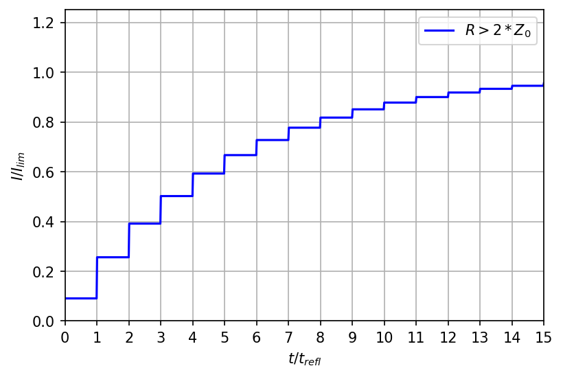
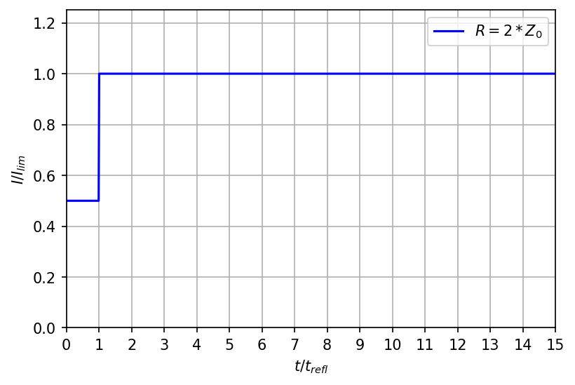
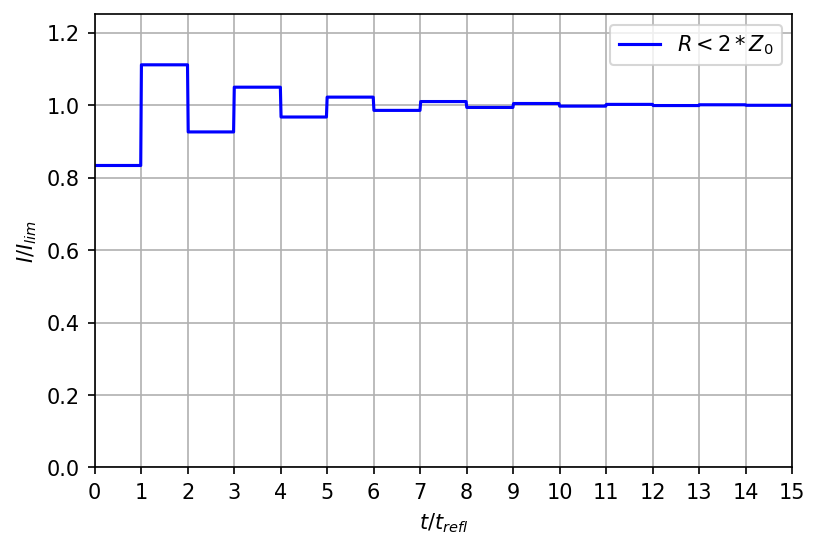
This is how it the current changes over time depending on the relative values of $R$ and $Z_0$:


When $R < 2 Z_0$, the lamp initially receives a fraction of the operating current $I_{lim}$, which then jumps up every second (every time a reflected wave comes back to the source) asymptotically approaching $I_{lim}$ from below.
When $R > 2 Z_0$, the current jumps above and below $I_{lim}$ with the amplitude of the jumps tending to zero.
$R = 2 Z_0$ is a special case where the current reaches $I_{lim}$ in a second (after a single reflection) and then doesn't change. (This is because the reflected wave is completely absorbed by the lamp and there is no re-reflection.) The initial current in this case is $\frac{1}{2}I_{lim}$.
Now back to the original question, can $R$ really be of a similar magnitude to $2 Z_0$ if we don't allow any other unrealistic assumptions besides the light second-long superconducting wires? Let's put some numbers on it. Suppose the wires are $a=2\ mm$ wide and positioned at distance $d=1\ m$ from each other. And the battery provides $\mathcal{E}=100\ V$ of EMF. What should the lamp's nominal power be in order to satisfy $R = 2 Z_0$?
$$ \begin{array}{ l l l } L' &= \frac{\mu}{\pi} \cosh^{-1}\frac{d}{2a} &= 2.5\ \mu H/m\\[0.5em] C' &= \frac{\pi\epsilon}{\cosh^{-1}\frac{d}{2a}} &= 4.5\ p F/m \\[0.5em] Z_0 &= \sqrt{\frac{L}{C}} &= 745\ Ω \\[0.5em] R &= 2Z_0 &= 1490\ Ω \\[0.5em] P &= \frac{\mathcal{E}^2}{R} &= 6.7\ W \\ \end{array} \\ $$
(Calculated using this page)
This makes one set of circuit parameters where the immediate current will be half the operating current:
- 100 V battery
- 6.7 W lamp
- 2 mm-wide wires spaced 1 meter apart

