1
$\begingroup$

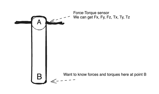
Suppose we have a rigid body with known length $r$ that is fixed at point $A$. We also have a force-torque sensor at point $A$. The body is fixed such that it doesn't move. We apply forces to point $B$ and get the values from sensor at point $A$. How can we translate the f-t values at $A$ to f-t values at $B$? enter image description here
UPD: Decided to write balancing equations to make it a bit more clear: enter image description here
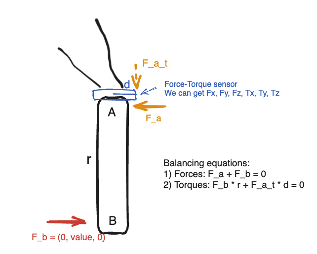
The rigid body is in the equilibrium and we press with some force $F_b$ at point $B$. We can see the values of the f-t sensor at $A$.

Thus:

There is one balancing force at $A$: $F_a$, and one balancing torque, which will be something like $F_{a_{t}}$ $\times$$d$ (depending on the design of the f-t sensor).

$$F_b = -F_a.$$

If $F_a = (0, value, 0)$ then opposing force $F_b$ will be equal to $(0, -value, 0).$

And if we can get values from the force-torque sensor at $B$, then we know the value of $F_a$ at $A$, which is equal to $(0, -F_y, 0)$.

Does this look correct?

$\endgroup$
8
  • $\begingroup$ I don't know if I understood. If the body is in equilibrium, the forces and torques at A must balance the forces and torques at B. Of course the weight of the body (body force) also must be taken in account. $\endgroup$ Commented Mar 27 at 0:02
  • $\begingroup$ Thanks! Am I right that, when the body is in equilibrium, forces at A balance forces at B and torques at A balance torques at B, and they do it separately, i.e. one equation for forces and one equation for torques? $\endgroup$
    – Heavenly T
    Commented Mar 27 at 1:05
  • $\begingroup$ yes, that is it. $\endgroup$ Commented Mar 27 at 1:07
  • $\begingroup$ Assume we apply force at B as shown on the picture above: F = (0, value, 0) Will the force at A be (0, -value, 0) and the torque at A be (value * len, 0, 0) ? $\endgroup$
    – Heavenly T
    Commented Mar 27 at 1:12
  • $\begingroup$ See equipollent torque ... $\endgroup$ Commented Mar 27 at 15:04

1 Answer 1

0
$\begingroup$

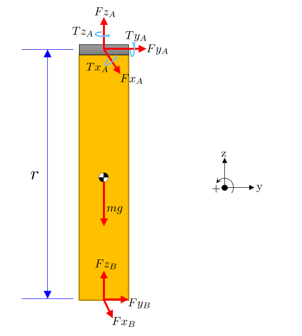
Your notation is confusing. Each component needs to indicate both the direction that it corresponds to, and the location it is associated with.

fig1

And using the equipollent torque $$ \vec{T}_A = \vec{r}_{\rm B/A} \times \vec{F}_B$$

you have the individual components of force

$$ \vec{F}_A = \pmatrix{ Fx_B \\ Fy_B \\ Fz_B - m g } $$

and torque

$$ \vec{T}_A = \pmatrix{ r\,Fy_B \\ \mbox{-} r\, Fx_B \\ 0 } $$

For the special case where $\vec{F}_B = (0,Fy_B,0)$ then $Tx_A = r\,Fy_B$ is the only surviving term.

Note that the weight of the part does not impart a torque on the support because the line of action of gravity goes through the support.

$\endgroup$
1
  • $\begingroup$ Thanks for such a clear explanation and pictures! $\endgroup$
    – Heavenly T
    Commented Mar 27 at 16:06

Your Answer

By clicking “Post Your Answer”, you agree to our terms of service and acknowledge you have read our privacy policy.

Not the answer you're looking for? Browse other questions tagged or ask your own question.