0
$\begingroup$

In a circuit with an AV power source $V$ and a zero-resistance ideal coil, the power from the source. $P_{in} = IV$ is equal to the rate of change in the magnetic energy $U_B$ stored in the coil. The source energy goes to the magnetic field: $P_{in}=\dot{U_B}$.

Does the source give energy to the coil? It seems so.

enter image description here

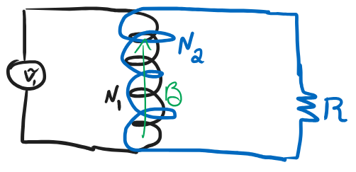
Now let's look at a transformer. On the left we have a source $V_1$ and an ideal zero-resistance coil with $N_1$ turns. On the right we have another ideal coil with $N_2$ turns, and a resistor $R$.

Is it in general true that the power from the source is equal to the power on the resistor? Meaning, $I_1 V_1= I_2 R$? Or are we missing the field energy term: $I_1 V_1= \dot{U_B} + I_2 R$?

Calculation yields:

$$ V_1/N_1=V_2/N_2 \\ V_2=I_2 R \\ V_1/N_1= \frac{\mu_0 A}{L} (N_1 \dot{I_1} + N_2 \dot{I_2}) \\ \dot{U_B}= \frac{\mu_0}{L}(N_1 I_1 + N_2 I_2)(N_1 \dot{I_1} + N_2 \dot{I_2}),\\ \\ P_{in}=V_1 I_1,\\ \\ P_R = {V_2}^2/R, \\$$

Does the field-energy term vanish in some limit or average?

enter image description here

$\endgroup$
4
  • $\begingroup$ Your calculations are unreadable. $\endgroup$
    – Bob D
    Commented Mar 21 at 15:47
  • 1
    $\begingroup$ The source giveth, the source taketh. In an ideal primary the energy given in half a cycle is taken back in the second half cycle. Is this the source of your doubt? $\endgroup$
    – Peltio
    Commented Mar 21 at 15:48
  • 1
    $\begingroup$ There’s no losses in an ideal transformer. $\endgroup$
    – Bob D
    Commented Mar 21 at 15:51
  • $\begingroup$ @Peltio How can we see from the expressions above that the energy is recaptured in the next half-cycle? $\endgroup$
    – Rd Basha
    Commented Mar 21 at 16:54

3 Answers 3

3
$\begingroup$

An ideal transformer is by definition lossless. This is why it is called "ideal": the ideal model ignores all the real-life losses that transformers experience.

These include resistive losses in the windings, hysteresis losses in the core laminations and flux leakage.

In the ideal model, all the energy temporarily stored in the magnetic field on each half-cycle is assumed to be losslessly recaptured in the next half-cycle.

$\endgroup$
2
  • $\begingroup$ How can we see from the expressions above that the energy is recaptured in the next half-cycle? $\endgroup$
    – Rd Basha
    Commented Mar 21 at 16:53
  • $\begingroup$ as the voltage in the primary falls and approaches the negative half cycle, the surrounding magnetic field collapses and thus induces a current flow in the secondary which captures the stored energy in the field. This is a fundamental fact of electromagnetic induction and cannot be directly derived from the diagram. $\endgroup$ Commented Mar 21 at 18:51
1
$\begingroup$

Let's consider an open secondary, so that you do not have the complication of a current flowing in it.

The primary winding is connected to an oscillating voltage source and some sort of limiting impedance (which could well be just the reactance of the primary coil), so a certain oscillating current will flow in the primary. This current will create an oscillating magnetic flux that is proportional to the number of turns of the primary winding, because each turn will contribute it's part to the total flux. Notice that in absence of any resistance (perfect conducting primary), voltage and current in the primary are in quadrature and the power is only apparent: whatever energy the source is giving the primary during half a cycle is taken back during the other half.

Just compute the instantaneous power p(t) = v(t) i(t) and integrate over one cycle.

All of this assumes an ideal (actually, a perfect) transfomer. In an actual transformer, with a magnetic core, you need to consider different kind of losses, such as the energy that has to be lost in magnetizing the core material and the ohmic losses in the windings.

The reason I wrote "perfect" instead of "ideal" is that an ideal transformer is a mythical beast like an unicorn which is so detached from real life that can be confusing. An ideal transformer works even at DC, and it has an infinite input impedance when the secondary is open (which is equivalent to consider an infinite inductance for the primary coil). This means that the current is zero when the secondary is open (so no power at all, at any time); but then how can you build the magnetic flux? Simple: the core has infinite permeability! No wonder people get confused by transformers.

$\endgroup$
1
$\begingroup$

For an ideal transformer, the core is assumed to be linear with infinite permeability. As a result, the energy stored in the magnetic core $\int\frac{B^2}{2 \mu}d\tau $ is zero. There is therefore no need to take it into account in the energy balance. So, the power supplied at the input is entirely supplied to the load at the output.

Edit :

If you consider this transformer as two mutually coupled circuits, you must introduce the inductance coefficients $L_1$, $L_2$ and $M$.

With proper conventions, the equations are: $u_1=L_1 \frac{di_1}{dt}+M \frac{di_2}{dt}$ and $u_2=L_2 \frac{di_2}{dt}+M \frac{ di_1}{dt}$

By multiplying the first by $i_1$ and the second by $i_2$ and adding the two, we find: $u_1 i_1=L_1 i_1 \frac{di_1}{dt}+M i_1 \frac{di_2}{dt}+ L_2 i_2 \frac{di_2}{dt}+M i_2 \frac{di_1}{dt} – u_2 i_2$

With the chosen conventions, $P_1 = u_1 i_1$ is the power supplied at the input and $P_2 = - u_2 i_2$ the power received by the load at the output.

We therefore have: $ P_1= P_2+ \frac{d}{dt}((1/2) L_1 i_1^2 + (1/2) L_1 i_1^2 + M i_1 i_2)$

By introducing the magnetic energy $E_m = (1/2) L_1 i_1^2 + (1/2) L_1 i_1^2 + M i_1 i_2$ :

$ P_1= P_2+ \frac{dE_m}{dt}$

In the case of a periodic regime, the mean of the time derivative is zero and it comes $ <P_1>= <P_2>$

Hope it can help and sorry for my poor english.

$\endgroup$
4
  • $\begingroup$ Thanks. What happens in the case above, when there is no core? $\endgroup$
    – Rd Basha
    Commented Mar 22 at 10:19
  • $\begingroup$ I added an edit to deal with the case of two circuits coupled by mutual inductance. $\endgroup$ Commented Mar 23 at 10:17
  • $\begingroup$ How do you show that the mean of the time derivative is zero? $\endgroup$
    – Rd Basha
    Commented Mar 23 at 11:50
  • $\begingroup$ This is only true for a periodic signal. Either you write the average of the derivative over a period and since it is periodic, the integral of the derivative is zero. Either you use Fourier series: the derivative of the constant part (the average) disappears during the derivation. $\endgroup$ Commented Mar 23 at 18:35

Your Answer

By clicking “Post Your Answer”, you agree to our terms of service and acknowledge you have read our privacy policy.

Not the answer you're looking for? Browse other questions tagged or ask your own question.