0
$\begingroup$

Hi Physics StackExchange!

Currently, I'm amidst research on a conceptually quite easy phenomenon: a magnetic force exerted on a (point) object by a coil with current I. In this research, I focus on the relation between magnetic force and distance x. Now, I have stumbled across two questions I cannot seem to figure out, mostly in mathematics.

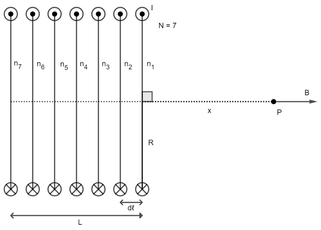
Let the point object P be directly in the centre axis outside the coil, as shown in the figure below. We assume there is no external force or field disturbing this situation, everything is stationary, the coil is perfectly distributed, and the current remains constant.

A coil with seven turns, length L, radius R and distance dℓ, imposing a magnetic field B on point P with distance x from the coil.

The derivation of a single enclosed loop imposing a magnetic field on a point with distance x, suppose only $n_1$ in the figure, I already have down. Namely:

$$B = \frac{\mu_0IR^2}{2 (R^2+x^2)^{\frac{3}{2}}}$$

I now wish to express the magnetic field in point P as a result of the entire coil with N loops and length L. In this example, I have seven loops drawn. By this, $d\ell = \frac{L}{N-1}$. So I now stand to reason to write:

$$B = \sum^N_{n=0} \frac{\mu_0IR^2}{2 (R^2+(x+n\frac{L}{N-1}^2)^{\frac{3}{2}}}$$

Would there be any way to express the magnetic field more elegantly than this?

My second question is regarding the abstraction of a coil as parallel, separate closed loops. If a coil is significantly wide with few loops, the angle at which the enclosed circuit imposes a magnetic field is significantly distorted. However, I have no idea how to show this mathematically. For the derivation of a single enclosed loop I omitted prior, we cut the loop in segments $d\ell$ (different from the $d\ell$ used before) and use symmetry to conclude the perpendicular magnetic field $B_\perp$ cancels out, leaving only the parallel magnetic field $B_{l//}$. If we then integrate over $d\ell$, we arrive at the first formula. How would one go about deriving the magnetic field of a more slanted, wide coil? I presume a three-dimensional equation for a coil is used, although I might be mistaken.

Thanks in advance for the help!

$\endgroup$
5
  • $\begingroup$ What is is that you are trying to do? Make a homogeneous magnetic field? The solutions for that can be easily found in the literature under "Helmholtz coil" and higher order "shimmed" magnetic coil configurations. The "distortion" of the field by the small angle of the individual windings does not matter in practice and it can be easily compensated for if necessary with more complex coil geometries I also agree with Dale, Biot-Savart is as simple as things get in terms of these kinds of problems. Try modeling a field with a magnetic material inside. Now that's hard. $\endgroup$ Commented May 15, 2023 at 15:52
  • $\begingroup$ Hi FlatterMann. As far as "What am I trying to do?' goes, we have quite a rubbishy put-together coil in dirty tape, of which we don't know the material used, the amount of winds or the dimensions (other than roughly measuring from outside), which was one of the experimental set-ups we were able to study in a Physics research class. The set-up is entirely ours to use, so I set out on the force applied to a metal plate, for which I first need to know the magnetic field. And if you don't mind, I find these derivations and modeling issues difficult enough as they are for the meantime, haha. $\endgroup$ Commented May 16, 2023 at 0:24
  • $\begingroup$ If you are trying to measure the force on a metal plate, then you didn't pay attention to the theory to begin with. The magnetic field is defined by the force on a current. Trying to estimate a field by the force on a magnetic material is a very messy and almost hopeless business, if you want any sort of precision. $\endgroup$ Commented May 16, 2023 at 3:01
  • $\begingroup$ @FlatterMann sorry to have you see it that way, yet save to say I have paid plenty of attention to theory as I scoured resource after resource. The set-up has its way to measure the downwards force, which is applied by the coil, directly related to the magnetic field, also confirmed by my professor. We are not trying to estimate the field by the force, we are trying to express the field by the parameters of the coil and the current. Then we want to relate the field to the force with a distance x between the coil and object. The precision may be doubtful, but we have yet to find alternatives. $\endgroup$ Commented May 17, 2023 at 9:59
  • $\begingroup$ I am simply saying that one can not measure a magnetic field with any precision (which is what you are complaining about) using the interaction with a ferromagnetic metal. If you want a precision measurement of the field, use a magnetometer. Linear hall effect sensors can be bought for less than a dollar these days, I have seen calibrated magnetic field sensors on sale for a few hundred dollars. If you want sub-ppm precision, you would use a nuclear or electron spin resonance setup. Your professor has to know this. $\endgroup$ Commented May 17, 2023 at 15:24

1 Answer 1

1
$\begingroup$

Would there be any way to express the magnetic field more elegantly than this?

Probably not. If you are looking at a point very far away then you could approximate the coil as a dipole, or if you are looking at a point right in the middle you could possibly approximate the coil as an infinite uniform cylinder of current. But from your drawing it seems that neither approximation will be great for your specific case.

How would one go about deriving the magnetic field of a more slanted, wide coil?

You could use this approach from "Modeling Magnetic Fields with Helical Solutions to Laplace's Equation" by B. Pollack, et al. which describes the field in terms of helical harmonics. I have not used this myself so I cannot comment on it in practice.

The other approach, which I have used, is simply a direct numerical application of the Biot-Savart law. It is "clunky" but it gets the job done.

$\endgroup$
1
  • $\begingroup$ Thanks for your reply! I am amidst using Biot-Savart, which is a tough cookie (clunky) indeed. Using x = Rcos(θ), y = Rsin(θ) and z = Rθtan(a) with a as the inclination of the coil, I got a vector integral expression for B. However, something I now don't get, which I will likely soon ask a question on Maths StackExchange for, I got an integral expression with ∫ [vector in terms of θ] / dθ^2. I know it most likely doesn't have an analytical solution and must be solved numerically, but I don't understand what ∫ f(x)/dx^2 means and how such things are calculated. Thanks for the help, though! $\endgroup$ Commented May 16, 2023 at 0:21

Your Answer

By clicking “Post Your Answer”, you agree to our terms of service and acknowledge you have read our privacy policy.

Not the answer you're looking for? Browse other questions tagged or ask your own question.