2
$\begingroup$

I am working on rewiring my old house. All of the second-floor lights, switches, and outlets are on a single circuit from the breaker. I recently installed ceiling fans in the bedrooms with wall switches on this circuit. In the bathroom on the same floor, there's a ground-fault circuit interrupter (GFCI) outlet, which sometimes trips when I turn off a ceiling fan (any of the three fans) using a wall switch in a bedroom (any of the three bedrooms). I recently asked a question about this on the Home Improvement StackExchange site, but my question there was mainly about whether this issue might be caused by a mistake I made in my wiring. I think I've learned that, no, this is not due to a wiring mistake, but rather it is somehow due to the inductive load of the ceiling fan motors, and this phenomenon is apparently referred to as a "nuisance trip" in the home repair/wiring community.

My question for the physics community is this: How, exactly, can switching off an inductive load in one part of a circuit cause a GFCI outlet to trip in another part of the same circuit? I've read that a GFCI outlet compares incoming current with outgoing current, and if there's a difference, it interprets that difference as being due to a ground fault and breaks the circuit. How is this happening when I switch off a fan somewhere else on the circuit? In other words, how is switching off the inductive load in one part of the circuit causing the GFCI to detect a non-zero net current through itself on a different branch of the same circuit? Or, to put it even more succinctly: What is the physics behind the "nuisance trips" in this particular case?

Potentially Useful Notes:

  • To reiterate, all lights, fans, switches and outlets involved in this question are on the same circuit from the breaker.
  • I have no load on the GFCI outlet, except for an LED night light plugged into it. (That is, no wires are connected to the load terminals of the outlet, so the outlet is not protecting the fans.)
  • Hence, the fans don't lose power when the GFCI outlet trips.
  • I know how inductors work (Faraday's Law, Lenz's Law, $\Delta V = -L\frac{dI}{dt}$, etc.). And I understand how switching off the load will cause a spark at the switch.
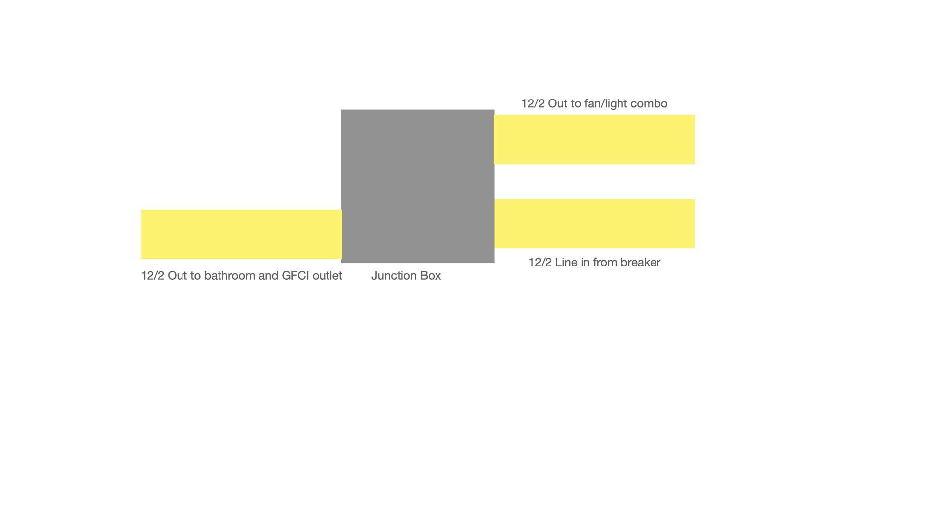
  • I have included a couple of basic circuit diagrams, in case they are helpful. The first shows how the ceiling fan is wired to the circuit, and the second just shows the basic idea of how power is being distributed from the breaker to the fans and the GFCI outlet. (This diagram shows only one fan, but there are other junction boxes with power going to the other fans as well.)

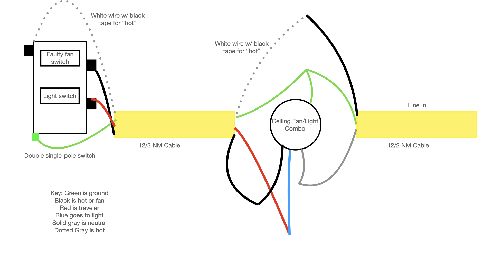
Ceiling fan/light combo wiring

Junction box showing line in, line out to fan, and line out to GFCI outlet

$\endgroup$
6
  • 2
    $\begingroup$ "I've read that a GFCI outlet compares incoming current with outgoing current..." Specifically, there is a current transformer with one core and three "windings." The hot and neutral make one turn each, parallel to each other, so that equal and opposite currents in those two turns cancel each other out, and there is no net magnetization of the core. The third winding is the sense coil, and it connects to a trigger circuit that trips the breaker if "enough" current is induced in the coil. $\endgroup$ Commented Jan 18, 2023 at 23:28
  • 1
    $\begingroup$ I cannot give an actual answer to your question. I can only guess that the trigger circuit in the GFCI somehow picks up the electrical noise that is injected into your home wiring by the ceiling fan. I would not assume that the noise gets in through the current transformer and the sense coil. There may be another route (e.g., through the trigger circuit's power supply.) $\endgroup$ Commented Jan 18, 2023 at 23:33
  • $\begingroup$ @BobD The fans and GFCI are on the same circuit in the sense that they all get their power through the same breaker in my circuit breaker box. However, when the line from the breaker gets up to the attic, it splits 4 ways via a junction box: three of those branches/legs go to the fans, and one branch goes to the GFCI outlet. So the GFCI outlet is not protecting the fans. $\endgroup$
    – Mike Bell
    Commented Jan 18, 2023 at 23:39
  • 1
    $\begingroup$ Would Electrical Engineering be a better home for this question? $\endgroup$
    – Qmechanic
    Commented Jan 19, 2023 at 4:21
  • $\begingroup$ @Qmechanic It might be. What's the protocol for doing that? I feel like we're getting somewhere with the answers so far proposed here, so I don't really want to delete this question, just in case I don't get any better answers from Electrical Engineering. Meanwhile, I also don't want to cause problems by having the same question posted on two different sites while waiting to see where I can get the best answer. $\endgroup$
    – Mike Bell
    Commented Jan 19, 2023 at 14:57

2 Answers 2

1
$\begingroup$

The outlet GFCI will interrupt any circuit connected to its load terminals, in addition to load plugged into the GFCI outlet itself, if the current to ground exceeds the nominal threshold of 5 mA rms. Normally only additional outlets are connected to the load terminals of the GFCI, such as kitchen outlets, but not lighting circuits or fan circuits. When you installed the ceiling fans in the bedroom, perhaps you tapped into an outlet that was protected by the GFCI? Even if you did, it is not clear why switching an inductive load would result in current to ground as current to ground is necessary to trip a GFCI.

Common causes of nuisance tripping of GFCI's can be found here: https://www.hendersonengineers.com/insight_article/understanding-gfci-nuisances/#:~:text=There%20are%20too%20many%20appliances,currents%20may%20trip%20the%20GFCI. Note that all the examples given in the link involve current to ground.

I suppose one possibility is that the arc produced by breaking an inductive load is somehow causing current to flow to ground via grounded metal parts of the switch in close proximity to the switch contacts. Arcing near insulating materials can also cause the formation of a carbonized path (carbon track) which in turn can support leakage current to ground. The first thing I would do is replace the switch to eliminate the possibility it may be faulty.

Another possibility is your GFCI may be a combination AFCI (arc fault circuit interrupter) GFCI device. Some AFCI's are designed to interrupt what is called a "series arcing fault" which does not involve current to ground. While they are supposed to differentiate between normal operational arcing that occurs in switches vs abnormal arcing, they have been known to nuisance trip on operational arcing.

Finally, as noted in the link, sometimes the problem is the GFCI is simply defective. You may want to consider replacing the GFCI to eliminate that possibility.

Hope this helps.

$\endgroup$
0
$\begingroup$

I suspect it's because the rapid, large voltage spike produces a spike of capacitive displacement current between one of the pair of protected conductors and something in the environment, like the ground wire. Thus, there's an unbalanced current on the pair, and that trips the GFCI.

Of course, this current is always present, but it's too small to trip the GFCI when the voltage varies slowly and stays within normal limits.

$\endgroup$

Your Answer

By clicking “Post Your Answer”, you agree to our terms of service and acknowledge you have read our privacy policy.

Not the answer you're looking for? Browse other questions tagged or ask your own question.