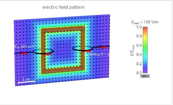
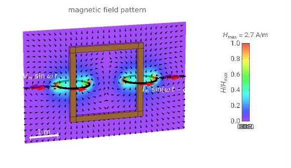
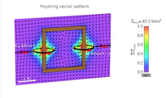
I've read in several places that the Poynting vector is directed from the primary to the secondary of a transformer (we assume here that the primary is the winding that provide the AC energy, while the secondary is just connected to some resistive load); the simulation below shows the electric, magnetic, and Poynting vector fields around a transformer. Assuming an ideal 1:1 transformer with identical windings, both the Electric and Magnetic fields are symmetric, so there is no way to know who is the primary and the secondary from these fields. But the Poynting vector is directed from the primary to the secondary, and I found that puzzling, because I can't figure out how the Poynting vector "knows that": indeed, assuming a power factor of 1 (ideal transformer), I can make the secondary primary, passing the same current as when it was a secondary, and then the secondary (that was the primary) will have the same current as when it was the primary. So, the currents being the same, how does the Poynting vector can decide who is the primary and the secondary?
-
$\begingroup$ I'm always surprised that there are questions that receive no upvote, but at the same time answers to that question that receive 4 upvotes or more: if an answer is so good that it deserve 4 upvotes, then the corresponding question that HAS LEAD to that answer should receive at least 1 upvote. That's my humble opinion. $\endgroup$– MikeTeXCommented Jun 9, 2022 at 12:08
5 Answers
The electric and magnetic fields are symmetric, yes, but across different axes. The combined electromagnetic field has neither symmetry. Consider that $/$ and $|$ have symmetries similar to your pictures of the fields, but when you put them together the result ($\hspace{.05em}/\hspace{-0.25em}|$) has lost those symmetries. In particular, flipping the electric field along the magnetic field's vertical line of symmetry swaps the primary and secondary (and flips the Poynting vector accordingly).
In terms of currents and voltages, the primary is the one where the current drops from higher to lower voltage and the secondary is the one where the current rises from lower to higher voltage. I.e. the coils are identified simply by using the sign of $P=IV.$ (See also: Poynting's theorem.)
Building on the excellent answer of HTNW (and also thanks to the comments of Ján Lalinský), I wish to elaborate a bit about inverting the primary and the secondary.
It is true that the primary and the secondary can be inverted while keeping the same currents, so that the same magnetic field is generated in both case. But regarding the electric field, it is also dependent upon the charge distribution on the surface of the wires, according to Jefimenko's equations (see note below); this charge distribution increases (more or less linearly in most cases) in the direction of the increasing potentials for the secondary of a transformer, and decreases in the direction of the increasing potentials for the primary. So, by inverting the primary and the secondary, keeping all currents the same, the charge distribution will invert its direction in both the primary and the secondary. By symmetry, the electric field will be inverted, and
as a result, the Poynting vector will still be directed from the (new) primary to the (new) secondary. That explains the apparent paradox.
Note: Jefimenko's equations connects the EM field with the sources: $$\mathbf{E}(\mathbf{r}, t) = \frac{1}{4 \pi \varepsilon_0} \int \left[\frac{\mathbf{r}-\mathbf{r}'}{|\mathbf{r}-\mathbf{r}'|^3}\rho(\mathbf{r}', t_r) + \frac{\mathbf{r}-\mathbf{r}'}{|\mathbf{r}-\mathbf{r}'|^2}\frac{1}{c}\frac{\partial \rho(\mathbf{r}', t_r)}{\partial t} - \frac{1}{|\mathbf{r}-\mathbf{r}'|}\frac{1}{c^2}\frac{\partial \mathbf{J}(\mathbf{r}', t_r)}{\partial t} \right] dV',$$ $$\mathbf{B}(\mathbf{r}, t) = -\frac{\mu_0}{4 \pi} \int \left[\frac{\mathbf{r}-\mathbf{r}'}{|\mathbf{r}-\mathbf{r}'|^3} \times \mathbf{J}(\mathbf{r}', t_r) + \frac{\mathbf{r}-\mathbf{r}'}{|\mathbf{r}-\mathbf{r}'|^2} \times \frac{1}{c} \frac{\partial \mathbf{J}(\mathbf{r}', t_r)}{\partial t} \right] dV',$$ where $\mathbf r$′ is a point in the charge distribution, $\mathbf r$ is a point in space, and $$t_r = t - \frac{|\mathbf{r}-\mathbf{r}'|}{c}$$ is the retarded time.
From these equations, it is not obvious that the E-field should be inverted if the charge distribution is inverted in the coils, but it should be possible to show the expected symmetry by a technical derivation.
-
1$\begingroup$ Total electric field is not generated only by surface charges, because there is also induced electric field due to changing current. "Electromotive force", in context of a transformer or any inductive device, is a term usually used to mean the induced electromotive force, not the force of conservative electric field characterized by difference of potential on terminals. $\endgroup$ Commented Jun 7, 2022 at 17:18
-
$\begingroup$ @Ján Lalinský. I tried to answer to your objection in an edit of my answer. $\endgroup$– MikeTeXCommented Jun 8, 2022 at 11:28
-
$\begingroup$ > "For electrical wires, the term $\frac{1}{c^2}\frac{\partial \mathbf{J}(\mathbf{r}', t_r)}{\partial t}$ is negligible" -- what is the reason for this statement? If this term is neglected, induced electric field is neglected. Induced electric field cannot be neglected when explaining how transformer works. $\endgroup$ Commented Jun 9, 2022 at 0:57
-
$\begingroup$ @Ján Lalinský. Indeed, you are completely right. I have rewritten my answer. Thank you again for helping me and pointing out my mistakes. $\endgroup$– MikeTeXCommented Jun 9, 2022 at 11:58
So, the currents being the same, how does the Poynting vector can decide who is the primary and the secondary?
The Poynting vector does not decide anything; it is just a quantity characterizing given EM field.
Energy in EM field near a transformer may flow in any direction, or not flow at all, depending on what is connected to which winding.
Usually we connect voltage source (hard-to-influence "voltage imposer") to one winding (called then the primary winding), and load (consumer) or nothing to the other winding (called then the secondary winding). EM energy then may or may not flow from the voltage source to the load depending on impedance of the device connected to the secondary, and in some cases it can even flow the opposite way. All depends on phases of current and voltage on the terminals, which in turn depends on behaviour of the devices connected there.
If the load is not a source of energy itself (the most common case), then the flow of energy is directed from the voltage source to the load.
If the load impedance is very high, there is almost no sustained power transfer, there is only oscillation of EM energy in the primary winding, charging up and discharging the ferromagnetic core.
If the load impedance is finite, there is some power transfer from the primary to the secondary and to the load. The most efficient transfer happens when impedance of the secondary is the same as that of the primary.
If the device on the secondary isn't a load, but a source of emf itself, then it is possible that power flows from the secondary to the primary and to the voltage source. This can happen when the device connected to the secondary can provide lots of its own energy (not the usual mode of operation).
-
$\begingroup$ You are right that the terms "primary" and "secondary" may lead to ambiguous readings of my question, as there are various sort of loads. Being not specified, I thought it was clear that my "primary" was the one that provides energy, while the secondary is simply connected to some purely resistive load. I will edit my question though. $\endgroup$– MikeTeXCommented Jun 8, 2022 at 9:26
Assuming we don't know which coil is primary and which is secondary. So we call the two coils coil 1 and coil 2 The voltage on coil 1 is $U_1$, and the voltage on coil 2 is $U_2$. Assuming that there is a current flowing into coil 1 from the high end of the voltage. The product of the complex conjugate of voltage and current is power. If the real part of the power in coil 1 is positive, it indicates that energy is flowing in from coil 1. Coil 1 is now a primary coil. Otherwise, coil 1 is a secondary coil. This method is equally effective for coil 2.
Don't ask Poynting vector. The energy flow from the primary coil to the secondary coil is not actually a Poynting vector. But the so-called mixed Poynting vector. This Poynting vector is the mutual energy flow part of the Poynting energy flow, not the self energy flow part. Because mutual energy flow is responsible for transferring energy flow from the primary coil to the secondary coil. On the contrary, self energy flow is reactive power and is not responsible for energy transfer from the primary coil to the secondary coil. for details please see:
-
$\begingroup$ "If the real part of the power in coil 1 is positive, it indicates that energy is flowing in from coil 1. Coil 1 is now a primary coil. Otherwise, coil 1 is a secondary coil." +1 for this part. Regarding your article, it's hard for me to believe Maxwell's equations are inexact. But I'm not really a physicist, so good luck. $\endgroup$– MikeTeXCommented Aug 6, 2023 at 6:30
-
$\begingroup$ @MikeTeX That's because my paper supports the existence of advanced waves. Due to the presence of advanced waves, the Maxwell equation is still correct, but the phase of the electromagnetic wave's magnetic field needs to be corrected. Additionally, for transformers, only the magnetic quasi state Maxwell equation is required. For the magnetic quasi state Maxwell equation, the magnetic field does not even need to be corrected for phase. Although most people do not recognize advanced waves. But there are famous scientists supporting its existence, including Einstein, Wheeler Feynman, Cramer $\endgroup$ Commented Aug 8, 2023 at 2:00
-
$\begingroup$ Do you have reference for Einstein etc. supporting advanced waves? well regarded books? Also, have you succeeded in convincing a professor of physics about your article? I'm curious, but there are so many theories by persons that think they have discovered something, that turn out to be just big errors of understanding right the physics.... $\endgroup$– MikeTeXCommented Aug 12, 2023 at 19:13
-
$\begingroup$ Einstein support idea that time is equal in two direction. Ritz against this idea. They had a debate in 1909: Walter Ritz and Albert Einstein. Zum gegenwärtigen Stand des Strahlungsproblems. Physikalische Zeitschrift. 1909, 10: 323–324. $\endgroup$ Commented Aug 27, 2023 at 17:53
The energy is transmitted by the Poynting vector, although it is correct, it is not very accurate. It should be said that for independent systems, such as simple circuits, which only include one power source and one resistor, transmission lines, waveguides, etc., the energy flow can be described by Poynting vectors. For discrete systems, the energy flow is transmitted by a part of the Poynting vector, the mutual energy flow. Discrete systems include the primary and secondary components of transformers, transmitting and receiving antennas, photon sources and sinks.
For discrete systems, the Poynting vector can be further subdivided into self energy flow and mutual energy flow. The energy flow between two parts in the system is mutual energy flow. For discrete systems, such as transformers. The Poynting vector of the primary coil belongs to the self energy flow. The Poynting vector of the secondary coil is also self energy flow. But there is an energy flow between the primary coil and the secondary coil. Self energy flow is reactive power. Mutual energy flow is the active power.
Our textbook today has not yet distinguished the mutual energy flow and self energy flow in the Poynting energy flow, so we cannot explain the energy flow from the primary to secondary of transformers. The following is a paper on the energy flow from the primary coil to the secondary coil of a transformer for reference.


