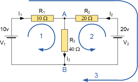
I was reading about Kirchhoff's Circuit Law and came across the following diagram:
Direction of the loop 1 and loop 2 makes sense to me as current (convention) is flowing from positive to negative. But it seems to me that the 3rd loop's direction is opposite to that of the 2nd one. Once $I_1$ splits at node A it will be at the opposite direction of $I_2$, what happens then?
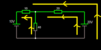
I went to Falstad and drew the same diagram to make a simulation, but the result confused me even more, here is the current flow I got:
This even contradicts the flow in the first image all current is going from positive to negative of the bigger voltage source and "ignoring" the $10\rm\ V$ one.
Falstad link for the animation
Any explanation is really appreciated!


