The dynamics of hanging bob from a free body
Problem Definition
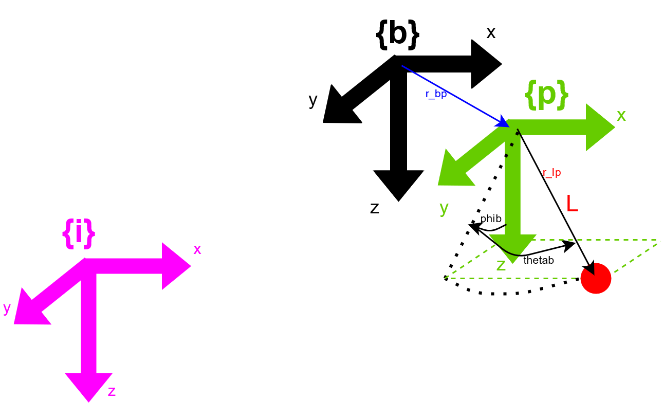
There are two objects considered. The parent body with position $\boldsymbol{r}_b$ at it's center of mass, and the bob suspended with a 2DOF U-join at location $\boldsymbol{r}_p$ with the center of mass a distance $\ell$ away. The location of bob is $\boldsymbol{r}_{\rm bob}$.

Kinematics
Positions
The parent body has orientation $\mathbf{R}_b$ relative to the intertial frame and thus the location of p is $$\boldsymbol{r}_p = \boldsymbol{r}_b + \underbrace{ \mathbf{R}_b \boldsymbol{r}_{p}^{b} }_{\boldsymbol{r}_{bp}} \tag{1}$$ where $\boldsymbol{r}_p^b$ is the location of the attachment point p in the body coordinates of b.
The location of the bob is $$\boldsymbol{r}_{\rm bob} = \boldsymbol{r}_p + \mathbf{R}_y(\theta)\, \mathbf{R}_x(\varphi)\, \ell \boldsymbol{\hat{i}}_z \tag{2}$$
Also the orientation of the bob is
$$ \mathbf{R}_{\rm bob} = \mathbf{R}_b\, \mathbf{R}_y\, \mathbf{R}_x \tag{3} $$
Velocities
The time derivative of (1) is
$$ \boldsymbol{v}_p = \boldsymbol{v}_b + \boldsymbol{\omega}_b \times (\boldsymbol{r}_p - \boldsymbol{r}_b) \tag{4}$$
Next we differentiate the orientation (3)
$$ \boldsymbol{\omega}_{\rm bob} = \boldsymbol{\omega}_b + \mathbf{R}_{b} \left( \boldsymbol{\hat{i}}_y \dot{\theta} + \mathbf{R}_y \boldsymbol{\hat{i}_x} \dot{\varphi} \right) \tag{5} $$
and use the rigid body transformations for the derivative of (2)
$$\boldsymbol{v}_{\rm bob} = \boldsymbol{v}_p +\boldsymbol{\omega}_{\rm bob} \times ( \boldsymbol{r}_{\rm bob} - \boldsymbol{r}_{p}) \tag{6} $$
Accelerations
The time derivative of (4) is
$$ \boldsymbol{a}_p = \boldsymbol{a}_b + \boldsymbol{\alpha}_b \times ( \boldsymbol{r}_p - \boldsymbol{r}_b) + \boldsymbol{\omega}_b \times ( \boldsymbol{v}_p - \boldsymbol{v}_b) \tag{7} $$
This is the tricky part, differentiating (5).
$$ \begin{aligned}\boldsymbol{\alpha}_{{\rm bob}} & =\boldsymbol{\alpha}_{b}+\mathbf{R}_{b}\left(\boldsymbol{\hat{i}_{y}}\ddot{\theta}+\mathbf{R}_{y}\boldsymbol{\hat{i}_{x}}\ddot{\varphi}\right)+\boldsymbol{\omega}_{b}\times\boldsymbol{\omega}_{{\rm bob}} +\\
& +\left(\boldsymbol{\omega}_{{\rm bob}}-\boldsymbol{\omega}_{b}\right)\times\left(\mathbf{R}_{b}\mathbf{R}_{y}\boldsymbol{\hat{i}_{x}}\dot{\varphi}\right)
\end{aligned} \tag{8} $$
And again a rigid body transform to differentiate (6)
$$\boldsymbol{a}_{{\rm bob}}=\boldsymbol{a}_{p}+\boldsymbol{\alpha}_{{\rm bob}}\times(\boldsymbol{r}_{{\rm bob}}-\boldsymbol{r}_{p})+\boldsymbol{\omega}_{{\rm bob}}\times(\boldsymbol{v}_{{\rm bob}}-\boldsymbol{v}_{p}) \tag{9}$$
Gravity & Inertia
Assume that all the bodies are under the influence of gravity $\boldsymbol{g} = \boldsymbol{\hat{i}_z} g$ and that the parent body has driving forces $\boldsymbol{F}_b$ and torques $\boldsymbol{\tau}_b$ defined at the center of mass of b.
The weight on each body is $$ \boldsymbol{W}_b = m_b \boldsymbol{g} \tag{10}$$ and $$\boldsymbol{W}_{\rm bob} = m_{\rm bob} \boldsymbol{g} \tag{11} $$
We also need the mass moment of inertia tensor of the b body described along the inertial basis vectors. If the MMOI in the body coordinates is $\mathbf{I}_b^b$ then
$$ \mathbf{I}_b = \mathbf{R}_b\, \mathbf{I}_b^b\, \mathbf{R}_b^\top $$
Equations of Motion
The connection can transfer forces between the two bodies, but not torques. So the net forces on the first body contain the equal and opposite forces acting on the second body. The connection force at the pivot is $\boldsymbol{F}_p$.
$$ \begin{aligned}
\boldsymbol{F}_b + \boldsymbol{W}_b - \boldsymbol{F}_p & = m_b \boldsymbol{a}_b \\
\boldsymbol{F}_p + \boldsymbol{W}_{\rm bob} & = m_{\rm bob} \boldsymbol{a}_{\rm bob}
\end{aligned} \tag{12} $$
We can define the torque at the pivot as $\boldsymbol{\tau}_p = \boldsymbol{0}$ so the rotational equations of motion do not need to contain this term. They do need to contain the equipollent torques of the forces resolved on each center of mass. This is the second tricky part here
$$ \begin{aligned}
\boldsymbol{\tau}_b - (\boldsymbol{r}_p - \boldsymbol{r}_b) \times \boldsymbol{F}_p & = \mathbf{I}_b \boldsymbol{\alpha}_b + \boldsymbol{\omega}_b \times \mathbf{I}_b \boldsymbol{\omega}_b \\ (\boldsymbol{r}_p - \boldsymbol{r}_{\rm bob}) \times \boldsymbol{F}_p &= \boldsymbol{0}
\end{aligned} \tag{13}$$
The second equation is that of a point mass at bob without any rotational inertia. As such, the connection force $\boldsymbol{F}_p$ must be parallel to the string as the cross product with the span of the string is zero.
Solution
Let us count the number of equations and the number of unknowns in (12) and (13).
- Equations - 4 vector equations means 12 component equations.
- Unknowns - Body b has 6 DOF, and the loading is unknown. The 6 unknown components are in $\boldsymbol{F}_b$ and $\boldsymbol{\tau}_b$, The connection force $\boldsymbol{F}_p$ has 3 unknown components, and the pivot has 3 unknown angles, 2 of which are only considered. So the total number of unknowns is 11.
To solve the above consider the connection force as having only 1 unknown (the force along the string) and disregard the rotational equation for the bob.
Make $\boldsymbol{F}_p = \frac{ F_p}{\ell} (\boldsymbol{r}_p-\boldsymbol{r}_{\rm bob})$ and count again
- Equations - 3 vector equations meas 9 component equations.
- Unknowns - 6 DOF of body b, 2 orientation angles, 1 tension force.
- Solution - solution is feasable as a system of 9 equations and 9 unknowns.
Summary
The equations for kinematics are
$$\begin{aligned}\boldsymbol{a}_{p} & =\boldsymbol{a}_{b}+\boldsymbol{\alpha}_{b}\times(\boldsymbol{r}_{p}-\boldsymbol{r}_{b})+\boldsymbol{\omega}_{b}\times(\boldsymbol{v}_{p}-\boldsymbol{v}_{b})\\
\boldsymbol{a}_{{\rm bob}} & =\boldsymbol{a}_{p}+\boldsymbol{\alpha}_{{\rm bob}}\times(\boldsymbol{r}_{{\rm bob}}-\boldsymbol{r}_{p})+\boldsymbol{\omega}_{{\rm bob}}\times(\boldsymbol{v}_{{\rm bob}}-\boldsymbol{v}_{p})\\
\boldsymbol{\alpha}_{{\rm bob}} & =\boldsymbol{\alpha}_{b}+\mathbf{R}_{b}\left(\boldsymbol{\hat{i}_{y}}\ddot{\theta}+\mathbf{R}_{y}\boldsymbol{\hat{i}_{x}}\ddot{\varphi}\right)+\boldsymbol{\omega}_{b}\times\boldsymbol{\omega}_{{\rm bob}}+\\
& +\left(\boldsymbol{\omega}_{{\rm bob}}-\boldsymbol{\omega}_{b}\right)\times\left(\mathbf{R}_{b}\mathbf{R}_{y}\boldsymbol{\hat{i}_{x}}\dot{\varphi}\right)
\end{aligned}$$
The equations for dynamics are
$$\begin{aligned}\boldsymbol{F}_{b}+\boldsymbol{W}_{b}-\boldsymbol{F}_{p} & =m_{b}\boldsymbol{a}_{b}\\
\boldsymbol{F}_{p}+\boldsymbol{W}_{{\rm bob}} & =m_{{\rm bob}}\boldsymbol{a}_{{\rm bob}}\\
\boldsymbol{\tau}_{b}-(\boldsymbol{r}_{p}-\boldsymbol{r}_{b})\times\boldsymbol{F}_{p} & =\mathbf{I}_{b}\boldsymbol{\alpha}_{b}+\boldsymbol{\omega}_{b}\times\mathbf{I}_{b}\boldsymbol{\omega}_{b}
\end{aligned}$$
The connection force is
$$ \boldsymbol{F}_{p}=\frac{F_{p}}{\ell}(\boldsymbol{r}_{p}-\boldsymbol{r}_{{\rm bob}})$$

