I know that for 2 separate single pendulums, the kinetic and potential energies are:
$$KE = \frac{1}{2}I(\dot\theta_1^2 + \dot\theta_2^2)$$
$$PE = 2mgl - mgl(\cos\theta_1 + \cos\theta_2)$$
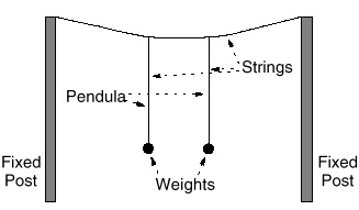
But I don't know how to incorporate the string in a coupled pendulum, as this is what connects the motion of the two pendulums.
1 Answer
The exact arrangement in your diagram is quite difficult to model because of an awkward coupling mechanism. The points of attachment at the horizontal supporting string are able to move in 3 dimensions, in the plane of the diagram and perpendicular to it, such that the lengths of each part of this string are fixed, as are the posts. So each support point has 2 degrees of freedom; for small amplitudes this can be reduced to 1.
The motions of the support points affects the KE of each swinging weight. (If amplitudes are small then changes in PE can be neglected.) Given these motions, it is fairly easy to write new KE terms. But it is more difficult to write the geometrical coupling between these two support point motions.
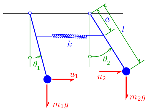
A much simpler way of modelling the coupling is as a spring connecting rigid rod pendulums which swing in the same plane, and each support point is fixed in position :

This enables you to write the energy terms much more easily. The essential features of the motion are the same as in the arrangement in your diagram.
The coupled motions are more interesting if you make the pendulums of different lengths and/or different weights.
See : Doubt in finding normal modes and natural frequency and also Coupled pendulums at half height

