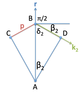
My textbook, Solid-State Physics, Fluidics, and Analytical Techniques in Micro- and Nanotechnology, by Madou, says the following in a section on X-Ray Intensity and Structure Factor $F(hkl)$:
We now mathematically derive the intensity profile of x-rays scattered from a crystal. The result, as Laue predicted, is the same as for visible light diffracted from an optical grating. When an incident x-ray beam travels inside a crystal, we assume that the beam is not much influenced by the presence of the crystal; in other words, the refractive index for x-rays is close to unity, and there is not much loss of energy from the beam through scattering, i.e., elastic scattering dominates!
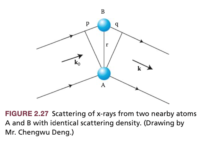
With reference to Figure 2.27, we assume two parallel plane x-ray waves of wavelength $\lambda$ and frequency $v$ (hence velocity $c = \lambda v$), scattered elastically from two nearby atoms $A$ and $B$ of identical scattering density. The wave vector for the incoming wave is $\mathbf{k}_0$ and that of the diffracted beam is $\mathbf{k}$. Because we assume elastic scattering:
$$|\mathbf{k}_0| = |\mathbf{k}| = k = 2\pi/\lambda \tag{2.31}$$
Scattering atom $A$ is at the origin, and scattering atom $B$ is at a distance $r$ away from the origin. The path difference, or phase factor, between the waves can be calculated from Figure 2.27 as:
$$p + q = \mathbf{r} \cdot (\mathbf{k} − \mathbf{k}_0) = \mathbf{r}\cdot \Delta \mathbf{k} \tag{2.32}$$
I found the derivation of 3.2 from figure 2.27 to be unclear, so I performed further research. I found the paper X-ray scattering (2016) by Ungar, Goran & Chen, Zhihong & Zeng, Xiangbing. Section 1, Brief introduction to X-ray scattering, says the following:
X-rays are scattered by electrons in matter. The classical interpretation is that an electron as a charged particle oscillates under the effect of the oscillating electric field of an incident X-ray beam, and hence emits an electromagnetic wave of the same frequency/wavelength. The intensity $I_e$ of the beam scattered by an electron is given by the Thomson equation:
$$I_e(r) = \dfrac{I_0}{r} \left( \dfrac{e^2}{mc^2} \right)^2 \dfrac{1 + \cos^2(2\theta)}{2} \tag{1}$$
Here $I_0$ is the intensity of the incident beam, $r$ the distance from the scattering electron, $e$ the charge and $m$ the mass of the electron, $c$ the speed of light, and $2\theta$ the scattering angle (angle between scattered and incident beam).
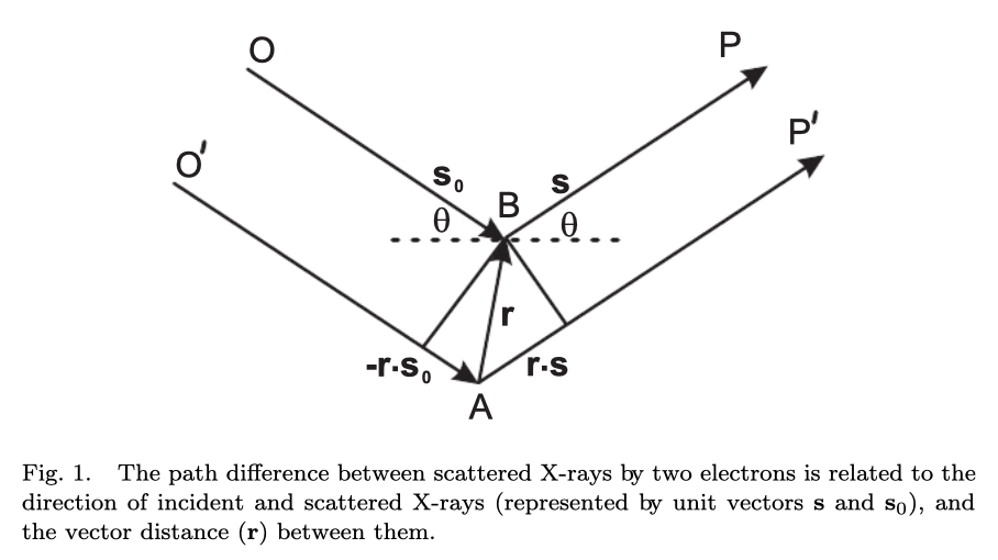
When the incident X-ray is scattered by two electrons separated by a vector $\mathbf{r}$ in space, in calculation of the combined scattered intensity the path length difference between the two scattered beams needs to be considered. According to Fig. 1, the path difference between the waves scattered on the two electrons is:
$$(O'AP' - OBP) = \mathbf{r} \cdot (\mathbf{s} - \mathbf{s}_0) \tag{2}$$
where $\mathbf{s}_0$ and $\mathbf{s}$ are the unit vectors of the incident and scattered X-rays. Hence, the phase difference is
$$\mathbf{r} \cdot (\mathbf{s} - \mathbf{s}_0) \cdot 2\pi / \lambda = \mathbf{r} \cdot \mathbf{q} \tag{3}$$
Here $\mathbf{q} = (\mathbf{s} - \mathbf{s}_0) \cdot 2\pi / \lambda$ is the wave vector of scattered light and $|\mathbf{q}| = 4\pi / \lambda \cdot \sin(\theta)$.
So the authors of the paper state that $\mathbf{s}_0$ and $\mathbf{s}$ are the unit vectors of the incident and scattered x-rays, which is in agreement with what the authors of the textbook state, which is that $|\mathbf{k}_0| = |\mathbf{k}| = k = 2\pi/\lambda$, which is unit length for a wave vector.
Previously in the textbook, the authors state the following:
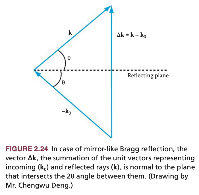
The magnitude of vector $\Delta \mathbf{k}$, from Figure 2.24, is then given as:
$$|\Delta \mathbf{k}| = 2 \mathbf{k} \sin(\theta) \tag{2.24}$$
This actually produces a calculation that agrees with that of the paper:
$$|\Delta \mathbf{k}| = 2k\sin(\theta) = 2(2 \pi / \lambda)\sin(\theta) = 4\pi / \lambda \cdot \sin(\theta)$$
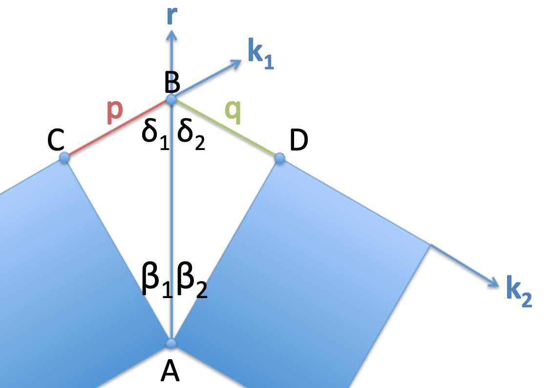
However, my confusion is that it is still not clear to me what $p$ and $q$ are supposed to be in the textbook, and, therefore, what $p + q$ is?
I would greatly appreciate it if people would please take the time to clarify this.

