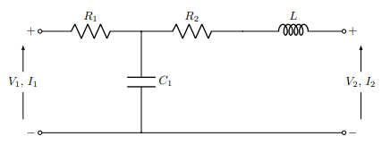
I'm a mathematics student, and it has been years since I last did current/voltage/resistor related subjects in high school. However, for one problem that I've encountered, I actually need to calculate a few of these. The problem is as follows:
The problem is the following. I want to find the voltage over the capacitor, and the current going through the capacitor. I found one source, telling me that I should treat the problem as if there is only one voltage source. First for $V_{1}$, and then for $V_{2}$, and combine the results. I set off to do this, starting with only considering $V_1$. I want to find the total resistance of the circuit, $R_{{\rm tot}}$, and from what I saw,
$$R_{{\rm tot}}=R_1+\frac{1}{\frac{1}{R_2}+\frac{1}{R_3}} \, ,$$
where $R_3$ would be the resistance in the "branch" (not sure about terminology) with the capacitor. However, there is no resistor in this branch. What does this mean for $R_{{\rm tot}}$, and the circuit as a whole? I feel like I might be taking the wrong approach, and I'm getting incredibly confused trying to figure out how this actually works. I would appreciate any advice on how to find the current through the capacitor, and how the voltage across the circuit actually works.

-
$\begingroup$ Welcome to the site. As a rule, all circuit posts should have a circuit diagram. Could you please attach a diagram? $\endgroup$– DanielSankCommented Oct 10, 2019 at 18:30
1 Answer
This is a "homework and exercise" problem that we generally don't provide solutions to, but only guidance. So here is some guidance for you to do additional research.
If I remember my filter concepts correctly (its been a while), this appears to be what is called a low pass filter, i.e., a filter that permits low frequency signals at the input (left side) through to the output (right side) while blocking high frequencies. The capacitor is low impedance at high frequencies and inductor is low impedance at low frequencies. So the capacitor shunts out high frequencies and the inductor blocks high frequencies. You should research the internet to learn more.
Since there is a capacitor and inductor in the circuit, you shouldn't be looking at the equivalent input resistance, but the equivalent impedance, which is the more general term that includes resistance.
The complex impedances of the capacitor and inductor, which depend on frequency, as well as resistance which does not depend on frequency need to be combined. You can look up the impedances for capacitors and inductors for sinusoidal ac voltages, and how to combine them with resistance.
If this is filter problem, V1 and V2 are not voltage sources, but represent the input (V1,I1) and output (V2,I2) of the filter. Otherwise the process of shorting each voltage source one at a time and adding the results is referred to as superposition.
If you wouldn't mind, could you verify for me whether the following is correct, so that I know if I am on the right track? From what I gathered, the current going through C1 is going to be V1/R1+V2/R2. I am suspicious of this because it looks remarkably simple. They, V1 and V2, are the voltages at the input and output.... In what way does that make it incorrect? –
It does look remarkably simple if it were based on your assumption that $V_1$ ad $V_2$ in the equation are the input and output voltages of the circuit. Unfortunately that assumption is incorrect.
It is incorrect because the voltages $V_1$ and $V_2$ in your equations are not the input and output voltages shown in the diagram, but are the voltage drops across $R_1$ and $R_2$, respectively. The following will explain.
Based on the circuit diagram, $I_1$ and $I_2$ are in the same direction through $C_1$, therefore the current in $C_1$ should be
$$I_{C_1}=I_{1}+I_{2}$$
Now the voltage drop across $R_1$ is
$$V_{R1}=I_{1}R_{1}$$
And the voltage drop across $R_2$ is
$$V_{R2}=I_{2}R_{2}$$
Putting these three equations together we get
$$I_{C1}= \frac{V_{R1}}{R_1}+\frac{V_{R2}}{R_2}$$
Which shows that the voltages in your equation are not the input and output voltages, but the voltage drops across $R_1$ and $R_2$.
Hope this helps.
-
$\begingroup$ Thanks. You are correct, this is an exercise, but the question I'm asking is basically just research to begin the exercise, not the exercise itself. If I'm understanding you correctly, you're saying that the concept of "total resistance" in this case isn't relevant, but rather its more generalised variant "impedance"? $\endgroup$ Commented Oct 10, 2019 at 20:14
-
$\begingroup$ @QuaereVerum Yes, that's exactly what I am saying. $\endgroup$– Bob DCommented Oct 10, 2019 at 20:33
-
$\begingroup$ If you wouldn't mind, could you verify for me whether the following is correct, so that I know if I am on the right track? From what I gathered, the current going through C1 is going to be V1/R1+V2/R2. I am suspicious of this because it looks remarkably simple. Hence my question. $\endgroup$ Commented Oct 11, 2019 at 12:37
-
$\begingroup$ @QuaereVerum What is $V_1$ and $V_2$ in your expression? $\endgroup$– Bob DCommented Oct 11, 2019 at 17:18
-
$\begingroup$ @QuaereVerum Because if they are the voltages at the input and output of the circuit, the expression is incorrect. $\endgroup$– Bob DCommented Oct 11, 2019 at 20:39
