3
$\begingroup$

I find quite difficult to interpret phase diagrams in general, for example I see people discuss them along the following lines:

  • Here we see the coexistence line between liquid-solid phases..
  • a tricritical point..
  • this section describes the stable solid phase..
  • in between these lines we have the metastable zone..

In other words, these diagrams seem to be telling us everything about a given system in a very compact way.

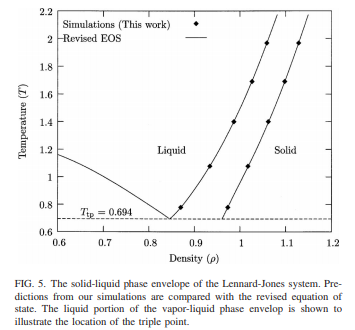
As an example, let us take the following phase diagram [source] shown in terms of temperature vs density for a Lennard-Jones fluid in three dimensions:

enter image description here


Questions:

  1. How does one interpret such a diagram in terms of the drawn curves and the outlined regions? Do all the points along the drawn lines correspond to phase transition points for different $T,\rho?$
  2. Is the region between the two near-vertical lines depicting a coexistence region? That is, any point would correspond to a Lennard-Jones fluid in a coexistence phase comprised of solid and liquid.
  3. What about the stable regions? For example, how can one know which sets of density values (and temperatures) correspond to stable solid phase of the fluid?
  4. I admit these are rather naive questions, but I really don't have a good grip on how to read such diagrams which are oh so important. Additionally, if you happen to know of good lecture notes teaching how to understand these diagrams together with explanations of the different kinds of points (tricritical, bicritical...), it would be very helpful.

Source: Mastny, Ethan A., and Juan J. de Pablo. "Melting line of the Lennard-Jones system, infinite size, and full potential." The Journal of chemical physics 127.10 (2007): 104504.

$\endgroup$
3
  • 1
    $\begingroup$ That is a very broad question. I'd start with any decent book on phase diagrams, particularly Porter and Easterling, Phase Transformation in Metals and Alloys. You might also look through chemistry.stackexchange.com/questions/19454/… and physics.stackexchange.com/questions/196686/… to see if those help (warning - answers by me). $\endgroup$
    – Jon Custer
    Commented Apr 23, 2019 at 13:58
  • $\begingroup$ @JonCuster Thanks a lot for the reference and links! I totally agree, this is quite broad, my attempt at making it acceptable within the common scope here has been to come up with a "simple enough" example, such that one could learn about the reasoning and interpretation from an example, instead of very general discussions. $\endgroup$
    – user929304
    Commented Apr 23, 2019 at 14:02
  • $\begingroup$ Here is somewhat a simple way of interpreting the diagram. Draw a horizontal line, for example T = 1.4, there are interceptions with liquid line and solid line. If you read density of the interception with liquid, that is liquid density. It is not coexisting state and there is no solid. The same is for the interception on the solid line. You can see the density of solid is larger, which makes sense. Between these two points is co-existing state where liquid and solid are blended and the density is in between the densities of liquid and solid. $\endgroup$
    – user115350
    Commented Apr 24, 2019 at 16:30

1 Answer 1

3
$\begingroup$

I agree with the commenters that this is a very broad question, and that you should start with some background reading, e.g. a textbook. Many standard Physical Chemistry texts give a good introduction to the phase diagrams of simple substances, and the Lennard-Jones system (although an idealized model) is fairly typical. The links provided by Jon Custer may also be helpful, but they are mainly concerned with systems of more than one component, so I would recommend starting with the simpler, one-component, case first.

I think that there's some value in doing what you wanted, and using the very specific example you have picked out from a simulation paper, to answer your questions. That paper is looking at the solid-liquid coexistence line: the "melting line". Plotted as a function of $T$ and $P$, it would indeed be a line (not, in general, a straight line, but a curve): along that line, the chemical potentials $\mu$ of the two phases would be equal, and the equation $\mu_\text{solid}(P,T)=\mu_\text{liquid}(P,T)$ will define a line in $P$-$T$ space. As you cross such a line, properties such as density $\rho$ change discontinuously (it's a first-order transition). Think of the lines in the $P$-$T$ diagram as marking these discontinuities. Like a crude topographical map, except that we don't mark out the contours of height, just the locations of cliff edges. A typical phase diagram in $P$-$T$ variables (but plotted, as is most common, with the temperature along the horizontal axis) can be found on the Wikipedia page.

If the phase diagram is plotted in temperature-density variables, the melting "line" becomes a coexistence region. In your picture, you'll see the dots on the two near-vertical lines come in pairs, which could be connected by horizontal lines. These are called "tie lines". They will be horizontal because the temperatures of the coexisting phases must be equal. The densities corresponding to the dots at the end of each tie line are those satisfying $\mu_\text{solid}(\rho_\text{solid},T)=\mu_\text{liquid}(\rho_\text{liquid},T)$. The general rule is, any state point $(\rho,T)$ in the two-phase region does not correspond to a stable phase, but to a mixture of the two phases $(\rho_\text{solid},T)$ and $(\rho_\text{liquid},T)$ , whose densities can be read off from the points at either end of the tie line. When plotted in other variables, in more complicated situations, it may be that the tie lines are not horizontal, and are actually drawn on the phase diagram, to help people make this construction.

The line going from $(\rho,T)\approx(0.84,0.694)$ up to $\approx(0.6,1.15)$ is the right hand boundary of the liquid-gas two phase region. If we extended the plot to lower density, the curve would continue to rise up to the critical point, at about $T=1.3$, and would then come down again, reaching $T=0.694$ at a very low density. There should be tie lines drawn horizontally across this region as well, corresponding to the coexistence densities of liquid and gas.

You'll see the horizontal dashed line at $T_\text{tp}=0.694$. This is the triple point, at which liquid, gas, and solid are all in equilibrium. Nothing much is shown below that temperature (this is not the interest of the authors of that paper). In fact, there will be yet another two phase region: solid-gas. This extends from a near-vertical line at very low density ($\rho_\text{gas}$) across to a near-vertical line extending downwards from roughly $\rho=0.96$ ($\rho_\text{solid}$). To the right of that region would be solid (one phase); to the left of that region would be gas (one phase).

The one-phase regions in the diagram are labelled "solid" and "liquid". The combinations $(\rho,T)$ of points in these regions correspond to a single stable phase. In the "liquid" region, for any temperatures higher than about $1.3$, it would be better to refer to the phase as a "supercritical fluid", since we do not distinguish between liquid and gas above the critical point.

I think there's not much more to be said about that particular diagram, but hopefully it has clarified things a bit. There is no tricritical point (you should not worry about those, until you've studied phase transitions more deeply) and in most circumstances phase diagrams show equilibrium phase boundaries rather than "metastable zones", so I would suggest putting those on the back burner too.

$\endgroup$
5
  • $\begingroup$ Many thanks! This has been most helpful, exactly along the lines I was hoping for. I have to still digest certain finer points you explained, but if I may already ask 1-2 follow up questions: i) on the labeled stable regions, let us for example pick the point $(\rho, T) = (1.1, 1.2)$ which is in the stable solid region, but what about the corresponding pressure? If we want to actually set a system up at that state, do we not need to know $P$ also? ii) with the triple point describing all 3 phases in equilibrium, does it mean at $T=T_{tp}$ any $\rho$ picked corresponds to 1 single stable phase? $\endgroup$
    – user929304
    Commented Apr 24, 2019 at 20:23
  • $\begingroup$ Thermodynamics tells us that the properties of a single phase are not independent of each other; all other intensive properties are determined by any two of them. So, there is a function $P(\rho,T)$, usually termed an equation of state. The Wikipedia page shows some representations of this as a surface in 3D; actually $P(v,T)$ where $v=V/N=1/\rho$. Or equally well, it represents $v(P,T)$. Think of the 2D phase diagram as a projection of this surface onto, say, the $(v,T)$ plane, or equivalently the $(\rho,T)$ plane. $\endgroup$
    – user197851
    Commented Apr 24, 2019 at 21:21
  • 1
    $\begingroup$ For your 2nd question, no, not that simple. There is a horizontal tie line joining the densities of the gas, liquid, and solid phases that are jointly at equilibrium. This tie line corresponds to a single point in the $P$-$T$ phase diagram. Beyond the ends of the tie line are (lower) densities corresponding to one phase (gas), and higher densities corresponding to one phase (solid). But intermediate densities must correspond to some combination of the three phases, with indeterminate amounts of each. (For two-phase tie lines, the relative amounts can be worked out from the average density). $\endgroup$
    – user197851
    Commented Apr 24, 2019 at 21:30
  • $\begingroup$ Thanks a lot, makes a ton of sense. Now I also see that in that very paper they have provided scripts that take $T,\rho$ and computes the pressure. Is providing such numerical scripts common when one cannot express the EOS as an analytical closed form expression of the thermodynamic variables? $\endgroup$
    – user929304
    Commented Apr 25, 2019 at 7:27
  • $\begingroup$ I would say that it is becoming more common. Actually in this case, I think that the EOS is expressible as a closed-form expression, it is just a fairly complicated one with a lot of parameters. Encoding this up in a program is a more reliable way of making it available, than expecting people to copy the expression, and a big table of parameters, by hand, from the paper. $\endgroup$
    – user197851
    Commented Apr 25, 2019 at 8:12

Your Answer

By clicking “Post Your Answer”, you agree to our terms of service and acknowledge you have read our privacy policy.

Not the answer you're looking for? Browse other questions tagged or ask your own question.