0
$\begingroup$

I have a small 4 watt water pump with an output port that accommodates 3/8" ID tubing.

I measured the flow rate while pumping to a static head height of 6 foot (see ladder photo).

The flow rate was 0.42 gallons per minute. (1/2 gallon in 70 seconds).

The pump was supplied (measured values) with 12.4VDC @ 310 mA giving 3.84 Watts.

How much of the 3.84 Electrical Watts was Work, and how much was Heat?

What I am going after how much heat is being generated by the pump. This is a concern because it is being used in a electronic cooling project where the pump will be submersed in the water.

I ran the pump in ambient air at 20° C, after one hour the case temperature was 25.2° C.

I had found a formula for calculating work using static head and flow rate. Was not sure 6 foot was the static head. Found an online calculator with a formula for Water Horsepower QxH/3960. Using a static head of 6 foot and 0.42 gallons/minute the formula result was 0.47 watts. I have no way of verifying this is correct. The other formulas required the watts which is the unverified parameter.

The water was pumped through a 7 foot length of 3/8" ID tubing.

Questions:

Is 0.47 Watts correct for the Water Horsepower?
Is the heat 3.84 - 0.47 = 3.37W ?

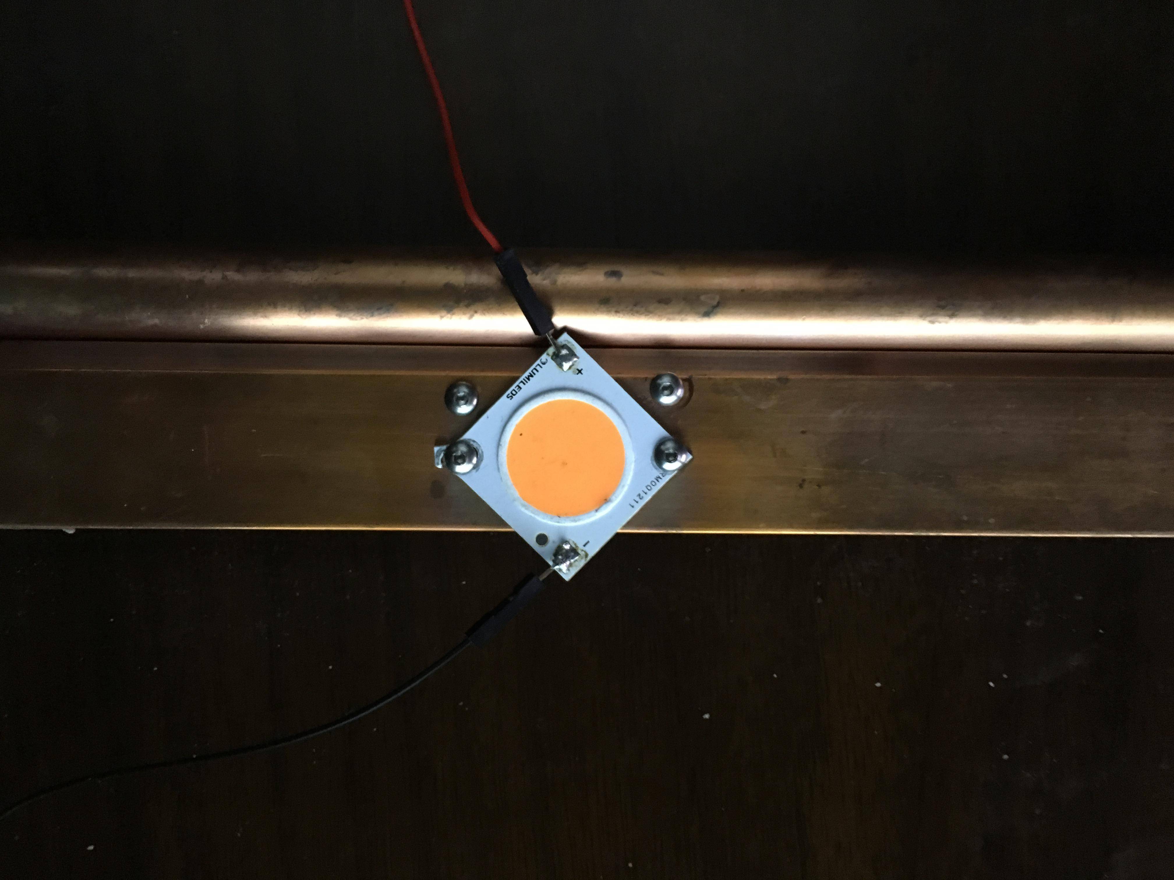
By logic the heat cannot be 3.37W if the pump temperature only increases by 5°. Working with the LEDs the total Wattage consumed by a single LED is typically 2-3 Watts which much is used in generating the radiant flux so the heat is 1-2 Watts and the LED gets much much hotter than this pump.


enter image description here


WHY?

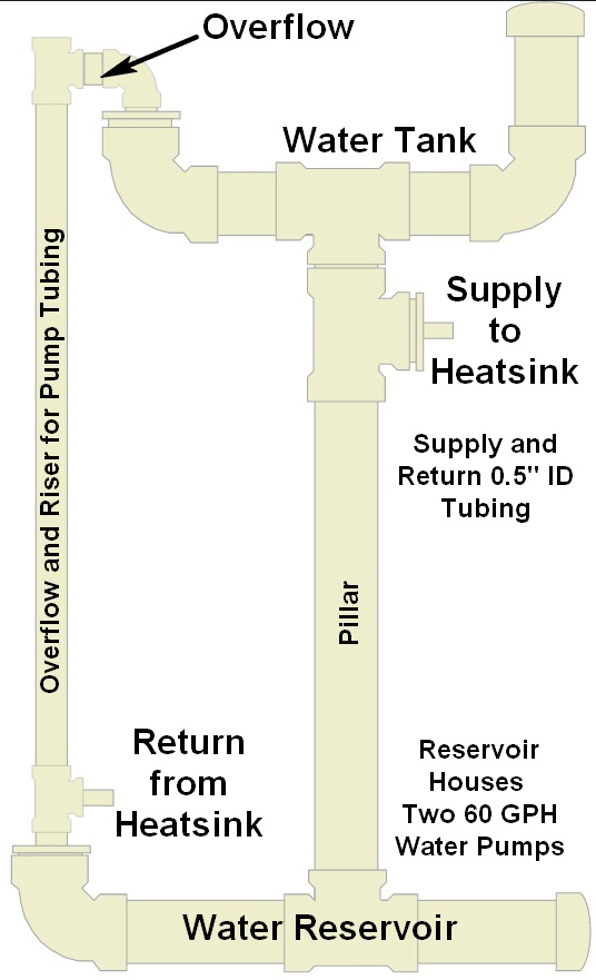
I was asked why. I am developing water cooled horticulture LED grow lighting. I am going to have a "water tower". It will be a closed system, there will be a water reservoir and a water tank. Both are made out of 4" PVC pipes. There is a 2" PVC pipe "riser" between the reservoir and tank. There will be water pumps in the reservoir pumping water from the reservoir into the tank. Their tubing will be routed through the 2" pipe riser. The 2" pipe will also double as an overflow. If for any reason the flow out of the tank is impeded, any excess water will just end back in the reservoir via the overflow pipe.

To cool the LED fixtures, the water must be kept cool. I wanted to know how much a water pump will contribute to the heat load. As more LED fixtures are added to the system the demand for water from the water tower is easily met by increasing the the flow rate from reservoir to tank.

THE HEATSINK

The heatsink is a solid 0.125" thick copper bar that is soldered to the side of a 1/2" water pipe. The water flowing from the tank to the reservoir will flow through this copper pipe.

enter image description here


THE WATER TOWER

The water tower is 5.5 foot tall so to fit in a horticulture research grow chamber. The center pillar is only to hold up the water tank. The pillar is capped below the "tee" with the supply stub. Nothing flows or is routed through the pillar, it is strictly structural.

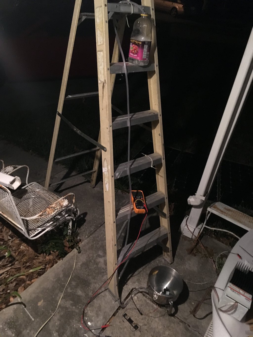
enter image description here

$\endgroup$

2 Answers 2

1
$\begingroup$

First we can estimate the loss for water flowing through the tube. 1. from flow rate and tube ID, the flow average flow velocity is 0.37m/s. 2. Reynolds number is thus 3980. 3. Assuming the tube's surface roughness 0.006mm~0.07mm, we can get friction factor 0.0098 to 0.0107. 4. Using length of 6 ft, we can get the flow loss 131~142Pa.

Then we can calculate the pump's shaft work using Bernoulli equation. This gives about 0.511~0.514W. This pretty close to what you get 0.47W.

But you are talking about the heat. Heat is generated by motor resistance. This might has little to do with above. So you can measure the resistance of your motor R, and use V^2/R to get the heat the motor can produce.

Now I don't understand, what's your purpose of doing these calculation.

$\endgroup$
7
  • $\begingroup$ Thank you. The resistance being the DC resistance of the motor windings? Which is different from the DC load calculated by the 12.4V / .31 Amp? I added some more photos and explanations regarding the project. Because the pumps are submersed in the water any heat generated will increase the temperature of the water. We want to find the most efficient pumps that generate the least heat per X gallons of flow. In order to evaluate the pumps, I first need to understand the problem. $\endgroup$ Commented Mar 3, 2017 at 6:11
  • $\begingroup$ It is an interesting project. Yes, the resistance is the resistance of windings. The current might not be 0.31AMP, which is the max value. You can measure the actual current then get the actual watts $W_a=V \times I$. This should be much lower than 3.84W. The heat is $W_h=\frac{V^2}{R}$. So I guess $0.47+W_h=W_a$. Of course this misses frictional loss. With today's technology, the frictional loss is low. $\endgroup$
    – user115350
    Commented Mar 3, 2017 at 6:52
  • $\begingroup$ The pump is rated at 350 mA, 310 and 12.4 were measured and the 3.84 W was calculated from these 2 values. That black bar by the foot of the ladder is a current shunt. When the static head was zero the current was 350 mA. The wattage is inverse to work and static head. You may now see why. You say this "should be much lower" but it is the actual. The heat cannot equal VxI because the Work must be accounted for. My question is actually: Is the heat 3.84-0.47? $\endgroup$ Commented Mar 3, 2017 at 16:08
  • $\begingroup$ What's the resistance value? $\endgroup$
    – user115350
    Commented Mar 3, 2017 at 17:20
  • $\begingroup$ Measured resistance is about 1 Mega-Ohm. The operating restive load is 40 ohm. $12.4\div 0.31$ $\endgroup$ Commented Mar 3, 2017 at 17:50
0
$\begingroup$

I think there is a better way to go about this.

You want to know how much heat will be generated, which should be relatively easy to test and measure.

Get a styrofoam cooler, which insulates well, and use that as your downstream reservoir. Set the your pump up to lift water, from the cooler, to a small upstream reservoir at the desired test elevation, and also provide some mechanism for the water to return to the cooler at the bottom. The goal is to get a recirculating system and so that you can run the pump for some time, and take temperature measurements.

Sure there will be some heat loss in the tubing, and in the upstream reservoir. You can try and insulate these parts if necessary.

By knowing how much water is in the system, and how fast the temperature rises, you can gauge how fast heat is put into the system by the pump.

$\endgroup$
1
  • $\begingroup$ That is often the case, easier to measure than calculate. I am actually the process of making a water tower. Added image to my post. $\endgroup$ Commented Mar 2, 2017 at 19:35

Your Answer

By clicking “Post Your Answer”, you agree to our terms of service and acknowledge you have read our privacy policy.

Not the answer you're looking for? Browse other questions tagged or ask your own question.