3
$\begingroup$

The induced voltage in the secondary coil of a transformer is given as $\frac { { N }_{ S } }{ { N }_{ P } } *{ V }_{ P }$ (where ${ N }_{ P}$ and ${ N }_{ S }$ are the number of turns in the primary and the secondary coil respectively, and ${ V }_{ P }$ is the voltage in the primary coil). I understand that to not violate the conservation of energy, the current in the secondary coil would need to be lessened by the same factor that the voltage is being increased with. Now, in a case where the secondary coil has twice the turns as in the primary coil, the voltage in the secondary coil would have to be twice as much of the voltage in the primary coil. Also, if both the coils were made of the same material with the same dimensions, the secondary coil would be at the very least be twice as long as the primary coil. Now, say the resistance of the primary coil was ${ R }_{ P }$, then the resistance in the secondary coil (${ R }_{ S }$) would be 2${ R }_{ P }$ (because ${ R }_{ S }=\frac { \rho (2L) }{ A } $). On applying the Ohm's law, the current in the secondary coil would come out to be the same as in the primary coil ($\frac { { V }_{ S } }{ { R }_{ S } } =\frac { 2{ V }_{ P } }{ { 2R }_{ P } } ={ I }$). The power in the primary coil was ${ V }_{ P }*I$ whereas the power in the secondary coil would be $2{ V }_{ P }*I$ which is twice the power as in the primary coil. This is clearly in disagreement with the fact that energy cannot be created. I know there's a mistake somewhere but I can't figure out where it is.

PS: For simplicity, the transformer which I considered was an ideal one.

$\endgroup$
1

1 Answer 1

2
$\begingroup$

Now, say the resistance of the primary coil was RP

If there is winding resistance, energy is lost and the transformer is not ideal.

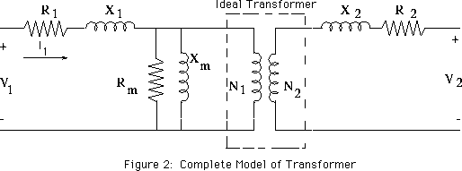
Consider the following circuit model (using ideal circuit elements) of a physical transformer (from an answer here):

enter image description here

Note that, in the middle of all this, is an ideal transformer that is lossless.

The resistors in series with the primary and secondary model the winding resistance of a physical transformer which is not lossless.

The inductors in series with the primary and secondary model the leakage inductance of the primary and secondary.

The parallel circuit elements across the primary model the losses due to core hysteresis and finite permeability.

$\endgroup$
6
  • $\begingroup$ Thank you for you informative comment to my answer which I have removed but unfortunately that has removed your comment.I am interested in the characteristics of your ideal transformer other than being 100% efficient.I assume that adding a load resistor to the secondary will mean that the induced emf in the secondary circuit will induce a current in the load resistor?Does the source see the resistance of the load divided by the turns ratio squared?For analysis of real transformer that is what you replace the ideal transformer with on the primary side?Would it also be true for a reactive load? $\endgroup$
    – Farcher
    Commented Feb 21, 2016 at 7:56
  • $\begingroup$ so do you mean that ohm's law isn't applicable in the case of a transformer? $\endgroup$ Commented Feb 21, 2016 at 8:45
  • $\begingroup$ @Farcher, an ideal transformer can be understood as two perfectly coupled ideal inductors in the limit as the inductances go to infinity (keeping the ratio of inductances constant). See, e.g., Ideal Transformer. So, for example, an ideal transformer transforms DC voltages and currents as well as arbitrarily high frequency voltages and currents without loss. The model in my answer clearly has a finite bandwidth as well as dissipative losses. But these do not come from the ideal transformer within in the model. $\endgroup$ Commented Feb 21, 2016 at 13:17
  • $\begingroup$ @AnindyaMahajan, Ohm's law doesn't apply to ideal inductors, ideal capacitors, ideal transformers etc. because they aren't ohmic devices. Another way to think of this is, for the ideal transformer, the winding resistance is zero so applying Ohm's law gives zero power dissipated (in the windings) for any finite current through. However, Ohm's law applies to, for example, the resistive load connected to the secondary. $\endgroup$ Commented Feb 21, 2016 at 13:23
  • $\begingroup$ @AlfredCentauri Thank you for all you very helpful comments. $\endgroup$
    – Farcher
    Commented Feb 21, 2016 at 14:10

Your Answer

By clicking “Post Your Answer”, you agree to our terms of service and acknowledge you have read our privacy policy.

Not the answer you're looking for? Browse other questions tagged or ask your own question.