0
$\begingroup$

enter image description here

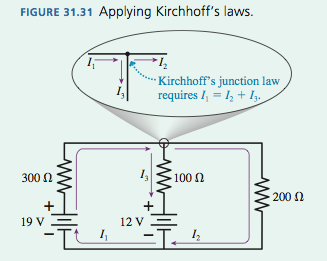
With this question, as with many tutorials of similar questions I’ve found online, my textbook only mentions three currents: $I_1$, which flows through the left loop from and to the 19 V battery, $I_2$, which flows through the right loop from and to the 19 V battery, and $I_3$, which flows through the middle section.

However, why can’t there be an $I_4$ which flows from and to the 12 V battery through the left loop, and an $I_5$ which flows through the right loop? In this diagram, it seems pretty clear that all the current comes from the 19 V battery. But about the current coming from the 12 V battery? Is there no current? (The subsequent analysis completely discounts the presence of any current from the 12 V battery, so I’m thoroughly confused.)

$\endgroup$
2
  • $\begingroup$ $I_2$ does not flow from and to the 19 V battery. It is the current through the 200 $\Omega$ resistor and joins other currents at the junction points. Only $I_1$ flows in the 19 V battery. Think of these currents as the total flow in each branch, not the whole complete loop. $\endgroup$
    – Bill N
    Commented Aug 1, 2017 at 0:20
  • 1
    $\begingroup$ lightweaver, there is another point to be made, and it's a mathematical point. If you correctly use Kirchhoff's rules, you will find that you can generate 3 and ONLY 3 independent equations for this circuit. To be solvable, you MUST have 3 unknowns for those equations. If you invent one or more unknowns than the minimum required, you will be unable to mathematically solve the problem. $\endgroup$ Commented Oct 9, 2018 at 18:17

6 Answers 6

0
$\begingroup$

Forget about the circuit details of the batteries and resistors for the moment and focus just on the circuit layout: You have three paths by which current can travel from the top to the bottom of the shown circuit. So you need three independent parameters, $I_1$, $I_2$, and $I_3$ to fully describe the current flow in this circuit. The directions of the arrows that you associate with $I_1$, $I_2$, and $I_3$ don't matter. If the arrow associated with, say, $I_1$ is drawn in the wrong direction then you will find that the current $I_1$ is negative when you work out the result, which would mean that the current if flowing in the opposite direction to that indicated by the arrow. So when you say "it seems pretty clear that all the current comes from the 19 V battery", that's actually not so. There is no assumption being made in the diagram that the directions of the current flows are determined by just the 19 V battery. Yes, the directions that the three arrows are pointing in are all consistent with a view of all the current being due to the 19 V battery, but that's not being assumed here. The current arrows can point in arbitrary directions. The only requirement is that you have to be consistent and keep the directions of all the arrows the same as you work though the problem.

$\endgroup$
0
$\begingroup$
  • If only the 19 V battery was present, there would be currents in all branches, right?
  • If only the 12 V battery was there, there would also be currents (but of different values) in all branches, right?

When both the 19 V and the 12 V batteries are present, they both contribute to all branches. The $I_1$, $I_2$ and $I_3$ in the diagram are the combined resulting currents, not only those coming from one battery.

$\endgroup$
0
$\begingroup$

The labelling of the voltages and currents does not matter as long as you stick to a convention.

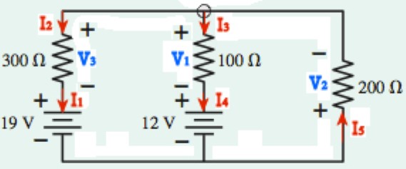
If you had used the passive sign convention you might have labelled the voltages and currents as shown in the circuit diagram below.

enter image description here

In this case using Kirchhoff's current law one gets these relationships between the currents

$$I_1=I_2,\, I_3=I_4\, {\rm{and}} \,I_2+I_3-I_5=0$$

Without doing the calculations suppose that in this case the current $I_5$ was found to be $-50\,\rm mA$.

Using the labels in your circuit diagram you would have found your current $I_2$ to be $+50\,\rm mA$.

So both methods produced the same magnitude for the current $(50\,\rm mA)$ and flowing in the same direction (into the top of the $200\,\Omega$ resistor and out of the bottom of the resistor).

You could have chosen the other currents and other current directions that you have suggested in your question to label your diagram butin the end you would end up with the same magnitude currents flowing in the same direction whichever set of labels you used on your circuit diagram.

$\endgroup$
0
$\begingroup$

First, saying current comes out of battery is not good. Current is continue flow of electrons in a circuit. The battery causes that flow.

The net current flowing in the circuit will be due to all the batteries in the circuit. By Superposition Theorem, the total current can be viewed as sum of currents caused by individual elements. And $I_1,I_2$ and $I_3$ shown in the circuit are net currents. For example, if the $12V$ battery is causing $10A$ to flow up in the middle wire and $19V$ battery is causing $20A$ to flow down in that wire, then value of $I_3$ will be $20 - 10=10A$. Thus there is no need for $I_4$ and $I_5$.

$\endgroup$
0
$\begingroup$

If your circuit has two “holes” through it, you need to define only two current loops (which may add (or subtract) in some parts of the circuit. Then you can write and solve two voltage loop equations. Your choice of current and voltage loops is arbitrary as as long as all parts of the circuit are included.

$\endgroup$
0
$\begingroup$

I agree with you yes you could have i4 and even i5.

But it doesn't matter.

Look at it another way - go for the current through components, now current i through the 19 Volt battery is the same as the current through the 300 Ohm resistor (has to be) so lets call that current ia

Then the current through the 12 Volt battery has to be the same as the current through the 100 Ohm resistor (has to be) so lets call that current ib

The only component left is the 200 Ohm resistor lets call the current through it ic

Now you can look at every junction where ia ib and ic go through and apply Kirchoff's law to them then write some simultaneous equations and solve for voltages.

What I do is assign currents to loops where there are components in series because the current through components in series has to be the same.

In your circuit there are five components (so five currents) but components in series makes it only three currents. The book didn't explain that to you.

$\endgroup$

Your Answer

By clicking “Post Your Answer”, you agree to our terms of service and acknowledge you have read our privacy policy.

Not the answer you're looking for? Browse other questions tagged or ask your own question.