1
$\begingroup$

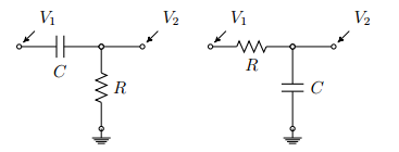
I have a very basic question about measurement of voltage output on some simple circuits. Considering the circuits of the figure:

enter image description here

Supposing one wants to measure the voltage output $V_2$, on the first circuit it will be $Ri$ the voltage drop accross the resistor while on the second it'll be $q/C$ the voltage drop accross the capacitor. In general it seems that if one measures the voltage output before some component the measurement will be equal to the drop of voltage accroos the said component. Why is that? I can't understand why this happens.

$\endgroup$
5
  • 2
    $\begingroup$ Actually, all the voltages are zero with respect to ground because there is no voltage or current source indicated in the diagram. You talk of measuring voltage at $V_2$ for example but it is not clear if you are measuring across the capacitor C ($V_1$ to $V_2$) or across the resistor $R$ to ground. Even still there isn't enough circuit to show a current path and with no current, and no voltage source, all voltages are at ground level. $\endgroup$
    – K7PEH
    Commented Jan 8, 2015 at 0:58
  • 4
    $\begingroup$ @K7PEH, it is typical for EEs to draw a simple network like the two examples above without the driving source indicated. And, this particular EE understands that, as drawn, $V_1$ is the independent (input) variable while $V_2$ is dependent (output) variable. See, for example: en.wikipedia.org/wiki/File:First_order_RC_circuit.svg $\endgroup$ Commented Jan 8, 2015 at 1:04
  • $\begingroup$ Would Electrical Engineering be a better home for this question? $\endgroup$
    – Qmechanic
    Commented Jan 8, 2015 at 1:12
  • $\begingroup$ @AlfredCentauri -- OK, I didn't realize the OP was an EE. Maybe he should have asked his question with regard to a 2-port circuit, I probably would have commented a little differently if at all. $\endgroup$
    – K7PEH
    Commented Jan 8, 2015 at 2:12
  • $\begingroup$ @K7PEH, In truth I'm not an EE, I'm a student of Physics, however in my course there are two lab terms related to electronics and those diagrams are from the book used. I'm really more interested in theoretical Physics, because of that I don't have much understanding of these topics. $\endgroup$
    – Gold
    Commented Jan 8, 2015 at 12:55

2 Answers 2

1
$\begingroup$

In general it seems that if one measures the voltage output before some component the measurement will be equal to the drop of voltage accroos the said component.

In this case, the voltage $V_2$ is a node voltage which means that is the voltage between the output node and the ground node. By definition, the ground node voltage is zero

$$V_0 = 0 \mathrm V $$

But, by inspection, the voltage across the resistor $R$ in the left-most circuit is simply

$$V_R = V_2 - V_0 = V_2 - 0 = V_2$$

Similarly, the voltage across the capacitor in the right-most circuit is simply

$$V_C = V_2 - V_0 = V_2 - 0 = V_2$$

Keep in mind that the output voltage must be taken across two nodes of a circuit. If there is just one circuit element connected between the two nodes, the output voltage is simply the voltage across that circuit element.

However, there may be a complex network connected between the output nodes so it isn't generally true that the output voltage is just the voltage across a single circuit element.

$\endgroup$
0
$\begingroup$

I like your question because it puzzled me a lot when I started to learn electronics. Here is the answer.

Just imagine a wire. There is a voltage V applied to its ends. What is the voltage at every section of the wire? If it is uniform wire, every meter of wire causes the same amount of voltage drop. Say, you divide the wire into n sections so that there is V/n voltages per every section or V/n * d if you measure voltage between d consequtive sections. You just add up d voltage drops together. When d=n, you measure voltage along the whole wire and it is not surprising that it equals to V/n * n = V the voltage that you apply. It is fine because you read what you apply.

Just take a very small voltage battery, make a short circuit using a very long wire and measure voltage, sliding with probes along the wire. You'll understand how voltages across non-intersecting intervals add up.

I am just explaining that voltage drop along the whole wire consists or breaks down into voltage drops at its sections. If there is a section which causes some voltage drop then the rest of the wire will expose less voltage drop so that total voltage drop equals the one that you apply at the ends. In your setup, capacitor and resistor amount almost all the input voltage that you apply to the wire. They take up most of the voltage drop so that there is almost nothing is left to drop at the rest of the wire because wire is considered an ideal conductor in this case and ideal conductors do not expose any voltage drops (unless they are loops and coils, which expose inertial 'resistnce' to the current build up, likewise 'resistence' of a massive body -- bodies, like swing, do not fall immediately on the ground despite of virtually no friction just because they have some inductance/inertia, which impedes the immediate acceleration of speed $v \to\infty$.)

Now, you say that element at the left end causes some voltage drop, whether it is $V_R$ or $V_C$. So, the rest of the wire, exposes $V_{in}$ - $V_{first_element}$ drop. You take it as your $V_{out}$. But $V_{out}$ is nothing more than voltage drop at the second half of the wire.

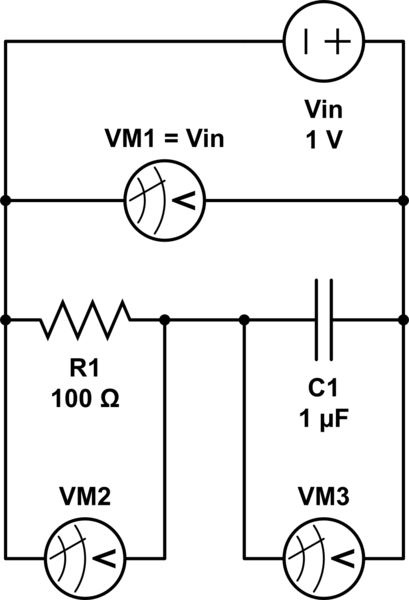
Here is illustration that is somewhat easier to understand. You apply the voltage to two series loads and measure the input voltage with VM1. It should equal the $V_{in}$ voltage that you apply. The two other voltages that you can get are the voltage drops at the two loads. Note that load on the right, whose voltage is measured by VoleMeter3, is what you define as $V_{out}$. You apply 'input' voltage that you have to both loads and read desired 'output' voltage from one of them.
schematic

$\endgroup$

Your Answer

By clicking “Post Your Answer”, you agree to our terms of service and acknowledge you have read our privacy policy.

Not the answer you're looking for? Browse other questions tagged or ask your own question.