4
$\begingroup$

enter image description hereenter image description hereenter image description here

This is my current(and most probably very incorrect) picture of how electricity comes in my house.

What I think of this picture is that, the transformer produces current in my house circuit (by induction), and that current is Alternate Current since the direction of current is changing through both coils continously. Now, how are Live and Neutral Wires different things? I mean current flows in both directions at 50Hz, so clearly both wires are 'live wires' in practice. But, in household circuits the neutral wire apparently doesnt have that much potentail as the live wire.

How is that possible? Is my picture missing some electrical components? Is my understanding missing some conceptual components?

Edit : I have added another picture, and another question arises, that if neutral is connected to the ground, then does it mean that when current flows through the circuit, ground and neutral wire both 'provide' electrons (as in their electrons get involved) which move/flow through the circuit?

Edit 2: I have added a GIF (very lazily made one). What I want to ask is that, are Earth and Neutral wire both contributing electrons as I have shown in the GIF? i.e Is earth also alternating with our whole cicuit? What should I change/add in the circuit's animation?

$\endgroup$
8
  • 2
    $\begingroup$ I thought the question was basic enough to be explained using 'physics laws' without any electrical terminology or concepts. $\endgroup$ Commented Dec 18, 2022 at 15:10
  • 1
    $\begingroup$ @RohitShekhawat After your last update, I do feel EE.SE is a better match. When you start getting into ground effects, the "physics laws" definitions get complicated quickly. As you've probably noticed in my last string of comments, I'm having to invoke effects that you likely wont hear about until 2nd year college level courses and giving example involving GFCIs, which are quite clever devices using a lot of fancy physics to do their job. EE's and electricians have to deal with these real life issues without constantly delving into such details, so they have good terminology for it. $\endgroup$
    – Cort Ammon
    Commented Dec 19, 2022 at 15:18
  • 1
    $\begingroup$ As a general rule in applied physics (such as electrical engineering), I find using the underlying physics is typically sufficient to understand the intended effects -- those we design to. Understanding the unintended effects typically requires an order of magnitude more theory because, by definition, it's all of the peculiar things we ignored when constructing the intended effects. I can explain how a transistor "works" in about 3 minutes. Explaining all of the gotchas is quite literally a 3rd year college course, and the physics for how to minimize them is 4th year. $\endgroup$
    – Cort Ammon
    Commented Dec 19, 2022 at 15:29
  • 1
    $\begingroup$ @RohitShekhawat Which of these sounds simpler to you: "this battery's voltage is 1.5 V" or "a line integral of the electric field between this battery's terminals, in the absence of a changing magnetic field, has a value of 1.5 V"? Using the word "voltage" makes things a lot easier, because if you just say "voltage," you don't have to understand the deep knowledge hidden behind every term. $\endgroup$ Commented Dec 19, 2022 at 17:51
  • 1
    $\begingroup$ Kirchhoff's circuit laws (which use electrical terminology) are much simpler than Maxwell's equations (the "real physics laws" that avoid most of that terminology). If you want to learn how electricity works, you should definitely study the simple thing (Kirchhoff's laws) before attempting to study the complicated thing (Maxwell's equations). $\endgroup$ Commented Dec 19, 2022 at 17:53

4 Answers 4

7
$\begingroup$

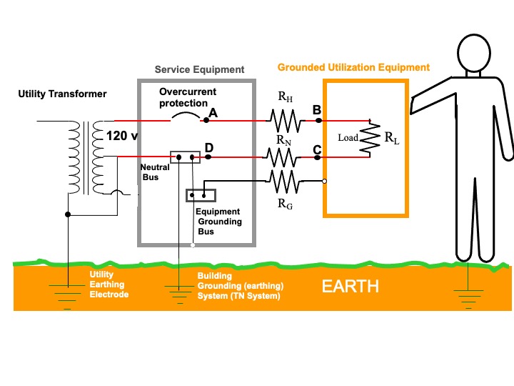
You are missing that both the neutral wire (formally called the grounded circuit conductor) in your house and one leg of the utility transformer are bonded together and to earth with grounding electrodes. The earth is considered as zero potential. Also missing is the separate equipment grounding conductor (third wire) in your home which is bonded to the neutral conductor in your service panel.

The Figure below shows the typical configuration for a TN (earthed neutral) system. It shows only one branch circuit.

Hope this helps.

enter image description here

$\endgroup$
9
  • $\begingroup$ Thanks a lot Bob (:D) On the basis of information provided by you, I have added another picture, and another question arises, that if neutral is connected to the ground, then does it mean that when current flows through the circuit, ground(i.e earth) and neutral wire both 'provide' electrons which move/flow through the circuit? $\endgroup$ Commented Dec 18, 2022 at 15:20
  • 1
    $\begingroup$ There is (normally) no current to ground. I've added a figure $\endgroup$
    – Bob D
    Commented Dec 18, 2022 at 16:22
  • $\begingroup$ Man, i have gained more information, but im still confused. Anyways ,thanks a lot again for helping. $\endgroup$ Commented Dec 18, 2022 at 16:33
  • $\begingroup$ What are you still confused about? $\endgroup$
    – Bob D
    Commented Dec 18, 2022 at 16:36
  • 1
    $\begingroup$ @RohitShekhawat Regarding your gif, why would the electrons in the circuit ATTRACT electrons from the Earth? $\endgroup$
    – Bob D
    Commented Jan 3, 2023 at 12:10
7
$\begingroup$

Voltage is not an absolute thing. Without a reference (e.g. ground) one cannot say that a wire is at any voltage. Voltage is measured between two points. I can say the voltage between the live and neutral wire is 120V. But, of course, we always do talk about the voltage of a wire, so what gives? To do this, we assign a reference point. We decide that the netural wire at the breaker-box is our reference, and all voltages are measured with respect to it. So, by definition the voltage of the neutral wire is 0V. And, since our earth ground is connected to the neutral wire, its voltage is also 0V (almost... there's some details there, but we'll ignore them at the moment).

We could pick any point in the system to be a reference. We could have picked either leg. However, from an electrical engineering design perspective, it's really helpful that everybody agrees. It is useful because we often want to design some surfaces to have very low voltages between them. For instance, we really don't want the surfaces of two metal lamps to have 120V between them. Someone touching both lamps at once would get shocked!

To do this, we have all agreed that if there's a surface a person might touch, it should be at 0V relative to that common reference at the breaker box. If someone gets shocked, the party at fault is the one who wasn't at that voltage. And we tie that to "earth" as well, so that non-electrical things like the floor are all at the same voltage as well.

So in the end, the netural line is at 0V beacuse we decided "things a human might touch are at 0V," and we all decided that we would let humans touch that line.

(And, because it's likely the next question, the difference between neutral and ground is current. It is agreed that all of the current should flow through the neutral wire, not the ground. Wires aren't perfect. They have some resistance to them. So if you have a high amount of current flowing through a circuit, the neutral near the wall socket is lifted slightly above 0V (It's still 0V at the breaker box). The ground is not supposed to ever have current, so it should be an agreed upon voltage level everwhere)

$\endgroup$
5
  • $\begingroup$ I have added a gif, can you take a look at it and help me with these questions. Are Earth and Neutral wire both contributing electrons as I have shown in the GIF? i.e Is earth also alternating with our whole cicuit? What should I change/ass in the circuit's animation? $\endgroup$ Commented Dec 19, 2022 at 13:00
  • 1
    $\begingroup$ @RohitShekhawat It will do something like what you drew, but very slightly. For animation purposes, you have the electrons in the ground moving about as much as those in the neutral wire. They should have less motion (less current). At the level of eletronics you are learning right now, current only flows when there is a loop. As drawn, there is no loop, so no current should flow. If you had drawn the grounding wire from the transformer (as you did in the second picture), then you could say there was a slight current through the ground. It's pretty low because the ground has a... $\endgroup$
    – Cort Ammon
    Commented Dec 19, 2022 at 15:06
  • 1
    $\begingroup$ ... reasonably high resistance (quite high in many cases). There's also an interesting effect called capacitance, which lets one store energy by storing charges on one side of a pair of conductors. Its effect is somewhat similar to that of a spring in a mechanical construct. You'll learn more about it later, but I find its helpful to know there's some "give" in real circuits early on (it's pretty easy to construct theoretical circuits that behave really badly, and effects like capacitance play a part in taming the wild badness). $\endgroup$
    – Cort Ammon
    Commented Dec 19, 2022 at 15:10
  • 1
    $\begingroup$ But all that being said, practically speaking you will find it hard to measure the electrons moving through ground. Its a very tiny current compared to the rest of the system. How small? Consider a GFCI. They're designed to cut power if they detect that current is flowing from live to ground rather than live to neutral. A GFCI is designed to trip at somewhere around 5 mA. So if you have a hairdryer running at 15 amps, and just 0.04% of the current went through the ground circuit rather than the neutral, you'd trip a GFCI. So when I say it's a really small effect, that gives you a ... $\endgroup$
    – Cort Ammon
    Commented Dec 19, 2022 at 15:13
  • $\begingroup$ ... sense of just how small $\endgroup$
    – Cort Ammon
    Commented Dec 19, 2022 at 15:13
2
$\begingroup$

How does neutral have lower potential than live wire? It's merely due to convention. The neutral wire is ulimately conductively connected to real earth through the building grounding electrode, and earth is, by convention, assumed to be at a potential of 0 volts. The live wire, obviously is not so connected, so consequently it must be at a higher (or lower) potential than earth.

The neutral wire is really only at 0 volts at the electrical panel ("service equipment") where it is physically connected to earth. When current flows in the neutral wire to complete an electrical circuit through a load, the "load end" of the neutral wire is actually at a non-zero potential. The magnitude of this potential is dependent on the electrical resistance of the neutral wire, $R_N$, and the amount of current flowing in it. In Bob's diagram, point D is at 0 volts because it is connected to earth with (normally) no current flowing from point D to earth. Point C, however, will be at a non-zero potential (with respect to earth) due to the load current flowing through $R_H$, $R_L$, and $R_N$.

Nominally and normally, no current flows through the earth from the utility transformer to the service equipment. Therefore, the earth does not provide electrons (aside from the random thermal electrons) to the current flowing in the load circuit, and virtually all the supplied electrons come from the neutral wire. But note that electrons do not travel very fast (drift velocity), and reverse their travel every 1/120 seconds (at 60 Hz), so they they also don't travel very far (probably less than a mm).

$\endgroup$
2
  • $\begingroup$ Thanks a lot for answerring. I have added a gif, can you take a look at it and help me with these questions. Are Earth and Neutral wire both contributing electrons as I have shown in the GIF? i.e Is earth also alternating with our whole cicuit? What should I change/ass in the circuit's animation? $\endgroup$ Commented Dec 19, 2022 at 13:00
  • 1
    $\begingroup$ The cntribution of electrons by the earth is very minimal, and nominally zero. We can't say it's identically zero, because random thermal motion of electrons at the junction of earth and neutral will guarantee that some electrons will enter the neural wire, but this would balanced by the same number of electrons leaving the neutral wire. The number of "exchanged" electrons is far far less than the current flow in the circuit. $\endgroup$
    – AndyW
    Commented Dec 19, 2022 at 20:57
1
$\begingroup$

Try thinking of it this way: Neutral is neutral, it is tied to the Earth via a wide and robust conductive path.

The Earth can absorb or provide lots of electrons before running out of them or places to put them. And if it comes close to running out, the power utility is always making more. So your electric devices can dump electrons into the neutral wire, or entice electrons out of it, without encountering significant resistance.

What your power utility does for you, sixty times each second, is to first force your hot wire to a negative voltage (relative to the Earth), then move it to zero, then force it to a positive voltage (relative to the Earth), then move it to zero, then start over.

When the hot wire is at the negative voltage, it pushes electrons into your device. These electrons drift through your device and out through the neutral wire, causing it to operate. This is intuitively easy to understand.

When the hot wire is at the positive voltage, it sucks electrons out of your device. This in turn draws electrons out of the neutral wire into your device. These electrons drift through your device in the other direction and cause it to operate.

Now, this model of how electricity works is so simplified that it is actually wrong. But it is a good place to start thinking from. You can see that the hot wire can push "electricity" through your devices into the neutral wire, and alternately suck "electricity" out of the neutral wire through your devices into the hot wire, all without moving the voltage level of the neutral wire.

$\endgroup$
2
  • $\begingroup$ Thanks a lot for answering. In your second last and third last parah, when electrons are flowing in and out of wires, does earth also take electrons in and out 50/sec? i.e Are neutral wire and earth working as a unit? Because if earth is not helping neutral wire, then neutral wire wont be 'neutral' i.e at zero potential. Again, thanks a loooot for answering. $\endgroup$ Commented Dec 19, 2022 at 7:15
  • $\begingroup$ I have added a gif, can you take a look at it and help me with these questions. Are Earth and Neutral wire both contributing electrons as I have shown in the GIF? i.e Is earth also alternating with our whole cicuit? What should I change/ass in the circuit's animation? $\endgroup$ Commented Dec 19, 2022 at 13:00

Your Answer

By clicking “Post Your Answer”, you agree to our terms of service and acknowledge you have read our privacy policy.

Not the answer you're looking for? Browse other questions tagged or ask your own question.