3
$\begingroup$

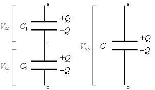
I am struggling to find an answer to this, hopefully relatively simple, question. I had a search on stackexchange but couldn't find anything helpful. We are learning about capacitors in Physics and I understand that when capacitors are connected in series, the charge stored in each is equal. My only issue with this is that, when the capacitors (lets assume there are two) have different capacitance, the potential difference across each will be different according to the formula $ V = \frac{q}{C} $. If this is true, and the potential difference across each is different, then why is there no potential difference between the two capacitors, as otherwise, charge would flow from one to the other and the resulting stored charges would not be equal.

One possible explanation for this behaviour that I can come up with is that since the magnitude of the charge on each face of the each capacitor is equal, the attractive force between the charge on the positive face of one capacitor and the negative charge on the face of the adjacent capacitor is balanced by the attractive force between that charge and the negative charge on the other face of the same capacitor. Is that correct?

I assume I must be misunderstanding something.

Edit 1

As I (clearly incorrectly) understand it, the electrons 'fill up' (as James Ngai Chun Tat put it) one plate (plate A) and as a result electrons are repelled away from the other plate (plate B) and so there is a difference in charge across the plates, resulting in a potential difference. As electrons are repelled from the positive plate (plate B), they move to the negative plate of the adjacent capacitor (plate C) and fill it up. As electrons collect on this plate, it becomes negatively charged. I would have thought that as plate B is positively charged and plate C is negatively charged, there would be a potential difference between the two (causing electrons to flow in the opposite direction). What is wrong with the model I have come to understand?

Edit 2

We were taught that when charging a resistor, as charge flows to the plate from the battery, negative charge builds up on the plate beside the battery. As a result, the potential difference between that plate and the negative terminal on the battery falls, resulting in an increasingly low current until eventually charge stops flowing altogether (when the potential difference across all of the capacitors is equal to that across the power supply). Is that right?

$\endgroup$
2
  • $\begingroup$ Where did you get the idea that the charge in them is equal? $\endgroup$ Commented May 26, 2013 at 20:58
  • $\begingroup$ What I meant was the difference in the charge between the plates is the same in each capacitor. Is that not right? $\endgroup$ Commented May 26, 2013 at 22:49

4 Answers 4

2
$\begingroup$

then why is there no potential difference between the two capacitors

It's not quite clear what you mean here but do understand that charged capacitors are electrically neutral.

When a capacitor is "charged", it is not electrically charged, it is energy charged in the same sense as when we say a battery is charged.

There is nothing mysterious about two series connected circuit elements having different voltage drops. Think of two series connected resistors with different resistor values.


I would have thought that as plate B is positively charged and plate C is negatively charged, there would be a potential difference between the two

You're forgetting something fundamental: The plates B and C along with the wire that connects them are conductors. But, for an ideal conductor, charge distributes itself so that there is no (static) potential difference across the conductor.

enter image description here

The voltage between the bottom plate of C1 and the top plate of C2 is zero precisely because a conductor connects the two plates.

$\endgroup$
1
  • $\begingroup$ Thanks, I do understand this much. Please see my edit to better explain my misunderstanding $\endgroup$ Commented May 26, 2013 at 22:46
1
$\begingroup$

Bear in mind that capacitance is a function of Area and distance between plates, Connecting all the capacitance in series effectively increase the distance between the plates thus decreasing the total capacitance under the same voltage When connecting them in parallel, across the same voltage but the effective area is increased, therefore the capacitance increased

I don't think you need to think too much detail about what the electrons are doing, You never make any sense by using classical mechanics or thinking to look at the circuit

To explain the whole picture would involve Quantum mechanics.

$\endgroup$
7
  • $\begingroup$ The electrons will fill up the plate until the capacitor is saturated, the stored charge will repel and prevent any more electrons approaching.. You need to think it this way perhaps $\endgroup$ Commented May 26, 2013 at 21:01
  • $\begingroup$ Thanks, you are right that I don't really need to understand what the electrons are doing (although one day, I hope to understand). Your comment has given me a better understanding of what is going on but I still don't quite understand why there is no pd between the capacitors. Please see my edit to better explain my misunderstanding $\endgroup$ Commented May 26, 2013 at 22:48
  • $\begingroup$ Nice use of the word 'understand' five times in my comment. $\endgroup$ Commented May 26, 2013 at 22:57
  • $\begingroup$ An easy explanation would be imagining the EMF as an energy source, and every point in the circuit after passing through the battery they gained potential, LIKE getting energy, if you like to think it this way, and passing through every resistor will consume their energy. but for capacitor, Between two plates,electrons One side being pulled away, and another side adding more electrons under the EMF of the battery, then after some time the electrons repulsion is built up , you can think that the charges built up prevent any more charge building up. $\endgroup$ Commented May 26, 2013 at 23:11
  • $\begingroup$ your teachers are correct on edit 2I'm not sure how far you have been taken about the idea of Potential difference. You only want to care about what's the Difference in potential, and remember there is a dielectric between the two plates, therefore one side charge BEING PUlled and One side being filled, surely there must be a Potential difference at these two points for this to happen, Remember ELectric field and potential difference are interconnected . And a battery is something about its chemistry... if you had studied chemistry before, you will know why pd was developed between terminals. $\endgroup$ Commented May 26, 2013 at 23:15
1
$\begingroup$

The charge on each capacitor, connected in series, is indeed equal! This is the fact that is used to find out the voltage across each capacitor. However, to find the charge, one must first find the equivalent capacitance of the two capacitors, which is given by $1/c = 1/c_1 + 1/c_2$. If you have a 1 farad ($c_1$) and a 2 farad ($c_2$) capacitor connected in series ($c = \frac{2}{3} \,\mathrm{F)}$, to a 3 volt battery, the charge that will flow $Q = vc = (3 x \frac{2}{3})C = 2C$, and the capacitors will charge to $V_1 = Q/c_1 = 2/1 = 2 \,\mathrm{V}$; $V_2 = Q/c_2 = 2/2 = 1 \,\mathrm{V}$. This is analogous to a 2 V battery on top of a 1 V battery.

The reason there is no potential from the bottom of the 2 V battery (plate B) to the top of the 1 V battery (plate C), is that the contact resistance is almost zero, and for practical purposes it is considered zero, so there is no PD! However, from plate A to plate D, there is a PD! It is the voltage across both capacitors (3 volts for my example). When the capacitors charge to 2C, the sum of voltage across both of them will equal the source voltage and they will stop charging.

$\endgroup$
0
$\begingroup$

Re your edit 1, if the system consisted solely of plates B and C you would be correct: the opposing charges would create an electric field (and potential difference) between them that would cause charge to flow.

However, there is more to the system than plates B and C. In particular, the charge on plate A creates an electric field that exactly cancels that on plate B (because the surface charge densities are equal and opposite) so the net electric field between B and C is zero.

In general:

  1. A surface charge density $\sigma$ causes a discontinuity in the electric field $\Delta E =\sigma/\epsilon$. (Think of a Gaussian pillbox around a bit of the surface.)
  2. How that discontinuity is distributed between the two sides depends on the geometry of the particular problem.
  3. For a traditional two-plate capacitor, the charges on the two plates are equal in magnitude and opposing in sign, and all of the resultant electric field resides between the plates.
  4. In fact, one can take item 3 as the definition of a two plate capacitor. If the surface charges do not exactly cancel, so electric field "escapes" from the capacitor, there must be another conductor somewhere with suitable charge density to terminate the "escaped" field (see item 1 above), and the capacitor is a more complicated 3-or-more plate affair.

Your geometry as drawn is not one of those more complicated cases. As Alfred Centauri notes, plates B and C are connected, so charges will flow until the electric field between them vanishes. That equilibrium is precisely where the charges on A and B are equal and opposite.

However, as a thought experiment, you could imagine the two capacitors approaching each other until plates B and C merged into a single plate. Then you would indeed have a 3-plate capacitor, with the charge on the middle plate =0 and the charges on the outer plates being equal and opposite. The electric fields would be equal in the two gaps (assuming identical dielectrics), and the total voltage would distribute according to the relative gap sizes, with more voltage across the larger gap.

$\endgroup$
3
  • $\begingroup$ If there is no resultant electrical field, why, when you connect plate A directly to plate B, does the capacitor discharge. I would have thought that if there was no field, there would be no potential difference between the plates $\endgroup$ Commented May 27, 2013 at 9:18
  • $\begingroup$ There is indeed an electric field and consequently a voltage between A and B, which would discharge if bridged by a resistor. My answer reconciled the lack of field between plates B and C with the polarization of charge between them. Do I understand your nomenclature correctly: the "top" capacitor consists of A and B, and the bottom of C and D, with B connected to C by a wire? $\endgroup$
    – Art Brown
    Commented May 27, 2013 at 16:49
  • $\begingroup$ yes, that is correct $\endgroup$ Commented May 30, 2013 at 23:00

Your Answer

By clicking “Post Your Answer”, you agree to our terms of service and acknowledge you have read our privacy policy.

Not the answer you're looking for? Browse other questions tagged or ask your own question.