5
$\begingroup$

I'd like to know the right formula to calculate torque of a quadrotor propeller (propeller pitch is constant) due to aerodynamic drag in terms of angular velocity $ \omega $. For the sake of my simulation I'm assuming APC 10x4,7 propellers. I'd like to refer to UIUC Propeller Data Site, so please assume only the set of data given there is available while answering. I know really little of aerodynamics, I'm planning to design a control system in Simulink later on, but would like to derive a non-linear mathematical model first.

Please note I need to use data from UIUC Propeller Data Site for APC 10x4,7, which means the propeller below. I'm guessing all is there to derive a formula $\tau_d(\omega)$, I just don't understand how to do it.

Top view of APC 10x4,7 propeller, taken from [UIUC Propeller Data Site](http://www.ae.illinois.edu/m-selig/props/propDB.html#APC) Side view of APC 10x4,7 propeller, taken from [UIUC Propeller Data Site](http://www.ae.illinois.edu/m-selig/props/propDB.html#APC)

EDIT: By now I figured out, lift force of a wing can be calculated as:

$ F_T = C_T \rho A \frac{V^2}{2} $,

where $C_T$ is lift coefficient, $\rho$ means air density, $A$ is wing total area and $V$ is relative air speed. I also asked a friend who told me, for a helicopter propeller this transforms into:

$F_T(\omega) = C_T \rho A r^2 \omega^2 = C_T \rho \pi r^4 \omega^2 $,

with $A = \pi r^2$ being the area of the rotor, $r$ being its radius and $\omega$ being the propeller's rotational velocity. I guess, assuming the latter formula is true, one could derive one for drag force from it substituting $C_D$ for $C_T$ and rotor blade's frontal area (its projection, rather) for $A$. Could this be right?

Thrust and drag coefficients from UIUC:

RPM    CT       CP
2377   0.1039   0.0431
2676   0.1058   0.0437
2947   0.1059   0.0437
3234   0.1083   0.0444
3494   0.1096   0.0450
3762   0.1121   0.0460
4029   0.1136   0.0466
4319   0.1155   0.0474
4590   0.1177   0.0484
4880   0.1199   0.0494
5147   0.1213   0.0500
5417   0.1228   0.0508
5715   0.1239   0.0513
5960   0.1253   0.0520
6226   0.1261   0.0524
6528   0.1274   0.0531

Geometry data from UIUC below. I believe, $c$ is aerodynamic chord length, $R = 0.127m$ (propeller radius), $\beta$ is propeller's pitch at the respective point. I believe I can calculate propeller's side area using simple quadratic integration rule. But first I need to know my reasoning is right.

taken from [UIUC Propeller Data Site](http://www.ae.illinois.edu/m-selig/props/propDB.html#APC)

r/R    c/R     beta
0.15   0.109   21.11
0.20   0.132   23.90
0.25   0.156   24.65
0.30   0.176   24.11
0.35   0.193   22.78
0.40   0.206   21.01
0.45   0.216   19.00
0.50   0.223   17.06
0.55   0.226   15.33
0.60   0.225   13.82
0.65   0.219   12.51
0.70   0.210   11.36
0.75   0.197   10.27
0.80   0.179   9.32
0.85   0.157   8.36
0.90   0.130   7.27
0.95   0.087   6.15
1.00   0.042   5.04
$\endgroup$
2
  • $\begingroup$ I think that $C_D$ fills a different function than $C_T$, but if you understood what they're referenced to you might be able to convert between them. I can't figure out from your post or the link what the other variables like $c$ and $R$ from the graph are. If you desire to use a non-linear correlation with your Simulink model, I believe you're going about it with the right approach, you just need to develop the wing drag concepts better so you can use the literature data. $\endgroup$ Commented Jul 13, 2012 at 13:33
  • $\begingroup$ I added some more data from UIUC. $\endgroup$
    – mmm
    Commented Jul 13, 2012 at 14:05

2 Answers 2

3
$\begingroup$

OK, I figured out all my mistakes and the results seem sensible now.

I was using wrong formulas and, first of all, was not using imperial units which is necessary with UIUC's data. The right formulas are:

$F_T(RPS) = C_T \rho n^2 D^4$,

where: $\rho [\frac{slugs}{ft^3}] = 0.0023769$ is air density, $n[RPS]$ is prop angular speed in revolutions per seconds, $D[ft] = \frac{10}{12}$ is prop diameter. For calculating torque, the below formula must be used:

$\tau(RPS) = \frac{C_P \rho n^2 D^5}{2 \pi}$.

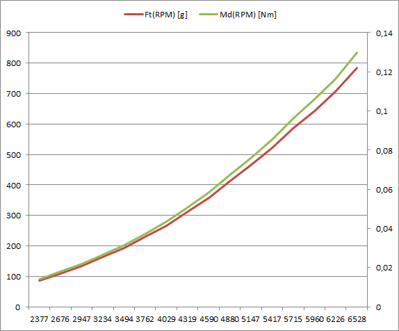
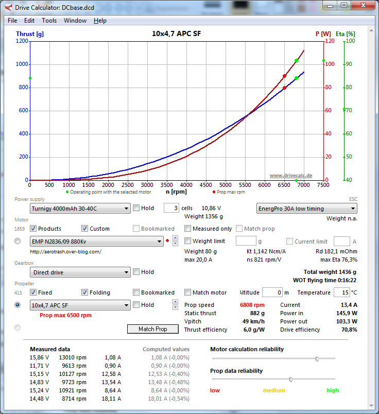
The results obtained seem sensible and in synch with e.g. Drive Calculator data. Some graphs and screenshots below. Of course, the results are all in imperial units, I converted them to SI for graphs.

enter image description here enter image description here

$\endgroup$
2
  • $\begingroup$ If you want numbers in SI units then just enter all variables in formula in SI units (air density = 1.225 kg/m^3). The force is then in N and torque in N.m. Values of C_T and C_P constants remains same as specified by UIUC when using SI units. Also, note that when using imperial units and air density = 0.00238, the force is in g in imperial units (torque is in g.ft). This is because air density is divided by g constant in imperial units. $\endgroup$ Commented Jan 17, 2017 at 3:26
  • $\begingroup$ I presume the $2\pi$ in the denominator is to convert the angular velocity from rad/s to hertz, is that not so? The torque equation one often encounters in literature uses the angular velocity in hertz so it would make sense here. However, since it is squared in the numerator, in the denominator, you should have $4\pi^2$ instead. Am I missing something here? $\endgroup$ Commented Oct 4, 2022 at 14:36
0
$\begingroup$

Just a shot in the dark. Assuming each propeller blade is a reasonably efficient airfoil, it should have a lift-to-drag ratio of (pick a number out of the air) 5. OK, so take the weight of the aircraft, divide by 5, and that should be the total drag on all the blades, at a radius of maybe 3/4 of the blade length. That should give a rough estimate of the torque.

$\endgroup$
2
  • $\begingroup$ Thank you for your help Mike, but I need to be more exact and refer to UIUC, as stated above. I added some details to my question, maybe you're able to help? $\endgroup$
    – mmm
    Commented Jul 12, 2012 at 7:01
  • $\begingroup$ Start by getting a baseline using momentum theory for power that only includes lift not drag. Then get the shaft power equivalent to that. Then you can get inertial measurement unit readings and record the propeller RPS and divide filtered yaw (+ direction) acceleration by filtered sum of the RPS^2 spinning in the +yaw direction - rps^2 in the -yaw direction. What you find at maximum torque for this quotient is the efficiency ratio. Your motor torque per rps^2 follows. $\endgroup$
    – atlex2
    Commented Aug 1, 2019 at 0:31

Your Answer

By clicking “Post Your Answer”, you agree to our terms of service and acknowledge you have read our privacy policy.

Not the answer you're looking for? Browse other questions tagged or ask your own question.