1
$\begingroup$

I have found that current always is from high voltage end of resistor to the low voltage end. But in battery sometimes it flows from + end of battery to - and mostly from - to +. I can find the direction in one loop circuit(with two butteries like this +--+) but its hard in multiloop circuits. What determines the direction?

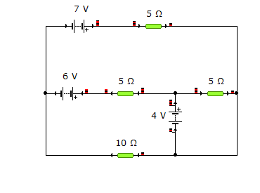
enter image description here

in this picture 7 volt battery and 6 volt battery have "almost" same condition, but why current is reverse in 6 volt one? is it because of the limit 10 ohm resistor gives to the circuit?

$\endgroup$
2
  • $\begingroup$ Could be that the - lead on the 7V is "-3.5V" and on 6V it is "-3V" so current flows from one to the other? $\endgroup$
    – Superbest
    Commented Sep 17, 2016 at 18:15
  • $\begingroup$ @Nemexia As I now have a circuit to look at I have been able to updated my answer. $\endgroup$
    – Farcher
    Commented Sep 18, 2016 at 12:49

2 Answers 2

2
$\begingroup$

If you connect two batteries and a resistor in series and the positive terminals of the two batteries are connected together then the battery with the larger emf will have current going out of its positive terminal and into its negative terminal.
The battery with the smaller emf will have current going out of its negative terminal and into its positive terminal and if it was a rechargeable battery it would be recharging with electrical energy from the other battery being converted to chemical energy.


Update

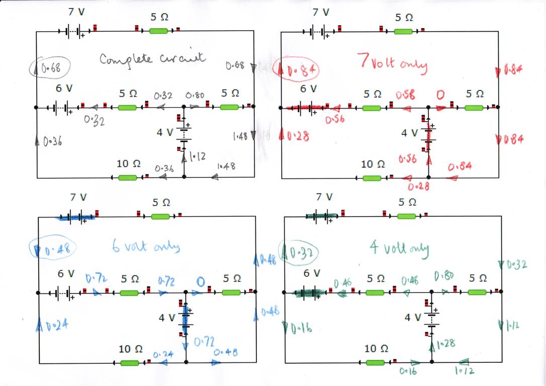
I have analysed you circuit and the currents in the circuit are a in to top left diagram.
enter image description here

Because the circuit components are linear the principle of superposition can be used to find out the contributions to the currents in the circuit due to each of the batteries.
In the top right diagram the $7$ volt battery was chosen and the $6$ volt and $4$ volt batteries were shorted out.
This was repeated for the other two batteries.

You will note that the ringed current value of $0.68$ in the top left diagram is the sum of the ringed currents in the other three diagrams and $0.64 + (-0.48) + 0.32 = 0.68$.
So the sum of the contributions to the current of each of the three batteries is equal to the actual current in the circuit.

The reason for doing this is to show that unless the circuit is relatively simple it is very difficult to predict which way the a current will flow throough a battery.

$\endgroup$
3
  • $\begingroup$ Yeah i know. My problem is with multiloop circuits where the method you mentioned doesnt work. Will post and example soon $\endgroup$
    – Nemexia
    Commented Sep 17, 2016 at 8:57
  • 1
    $\begingroup$ One of the things to remember about circuit analysis is that you can arbitrarily choose a current direction and then if you do your analysis if the value of the current is positive then you made the correct choice for the current direction but if the value comes out to be negative then you made the wrong choice but now you know in which direction of the current is. So make a guess about the current direction and then do the sums. $\endgroup$
    – Farcher
    Commented Sep 17, 2016 at 9:08
  • $\begingroup$ edited question $\endgroup$
    – Nemexia
    Commented Sep 17, 2016 at 15:44
2
$\begingroup$

Its very easy. You cut out the 6V battery of the circuit. Then you apply Thevenin's theorem to the remaining terminals, meaning that you can consider the remaining circuit as a series connection of a virtual battery and a resistor. Then, if the polarity of this virtual battery is opposed to the 6V battery and its voltage is larger than 6V, you will get a current flow against the normal battery current flow given by the difference of battery voltages divided by the Thevenin resistance.

$\endgroup$
1
  • $\begingroup$ wow Thevenin's theorem was awesome! $\endgroup$
    – Nemexia
    Commented Sep 18, 2016 at 18:21

Your Answer

By clicking “Post Your Answer”, you agree to our terms of service and acknowledge you have read our privacy policy.

Not the answer you're looking for? Browse other questions tagged or ask your own question.