1
$\begingroup$

I'm currently writing a paper on designing a system which can detects if there's a leakage between two certain point of water pipe. I'm using MPX5100 differential pressure sensor as the measurement sensor. Here's a picture how's the sensor will be placed

Since I have not enough knowledge about fluids dynamic (and my background is Computer Engineering), I need to do a calculation first to prove that there's a pressure drop when a leak appeared at the water pipe

I've checked other questions such as these: How to calculate leakage flow in a horizontal pipe? and How to calculate pressure loss due to water leakage from a hole in a pressurized unit. And they proved that it's a fact that there's a pressure drop when a leak appears in a water pipe

What law or theory that I should use to support my paper? Assuming :

  • The flow is incompressible, and laminar
  • The length of pipe to be used is fixed
$\endgroup$
9
  • $\begingroup$ You could apply Bernoulli's principle. $\endgroup$
    – fibonatic
    Commented Aug 13, 2016 at 4:02
  • $\begingroup$ Are you looking for an actual formula or just an argument to show that there will be drop in pressure if there is leakage? $\endgroup$
    – Deep
    Commented Aug 13, 2016 at 7:17
  • $\begingroup$ @Zero i'm actually looking for an argument, proving that there is a pressure drop if a leak happened. But my supervisor advised that I should put some formula, so that I can support my arguments $\endgroup$ Commented Aug 14, 2016 at 9:10
  • $\begingroup$ There needs to be a little bit more information. Example, can you isolate the length of pipe you plan to check for the leak. That is, are there valves that you can close off. If so, a simple pressure gauge installed between the points will indicate the pressure drop. If you know the pipe size and length that is isolated, $\endgroup$ Commented Aug 15, 2016 at 13:18
  • $\begingroup$ Cont't of the above. Knowing the pipe size, length and initial pressure, you can determine size of the leak by measuring the pressure reduction over a specific period of time. $\endgroup$ Commented Aug 15, 2016 at 13:21

1 Answer 1

1
$\begingroup$

You must assume something to be constant in the pipe: either the flow rate or the pressure at some point upstream of the pipe (say where pump is located). I will show you the argument for the case where pressure at some point upstream of the leak is constant. You work out the other case.

Let us assume laminar flow. In this case, total pressure drop is proportional to flow rate, $\Delta p=RQ$, where $R$ is resistance to flow (read up Darcy-Weisbach equation; in laminar flow friction factor is inversely proportional to flow speed). When such a linear relationship does not hold, the argument runs on similar lines to what I outline here (I shall leave that to you, again).

So now the flow in pipe may be represented by the following circuit diagram: enter image description here
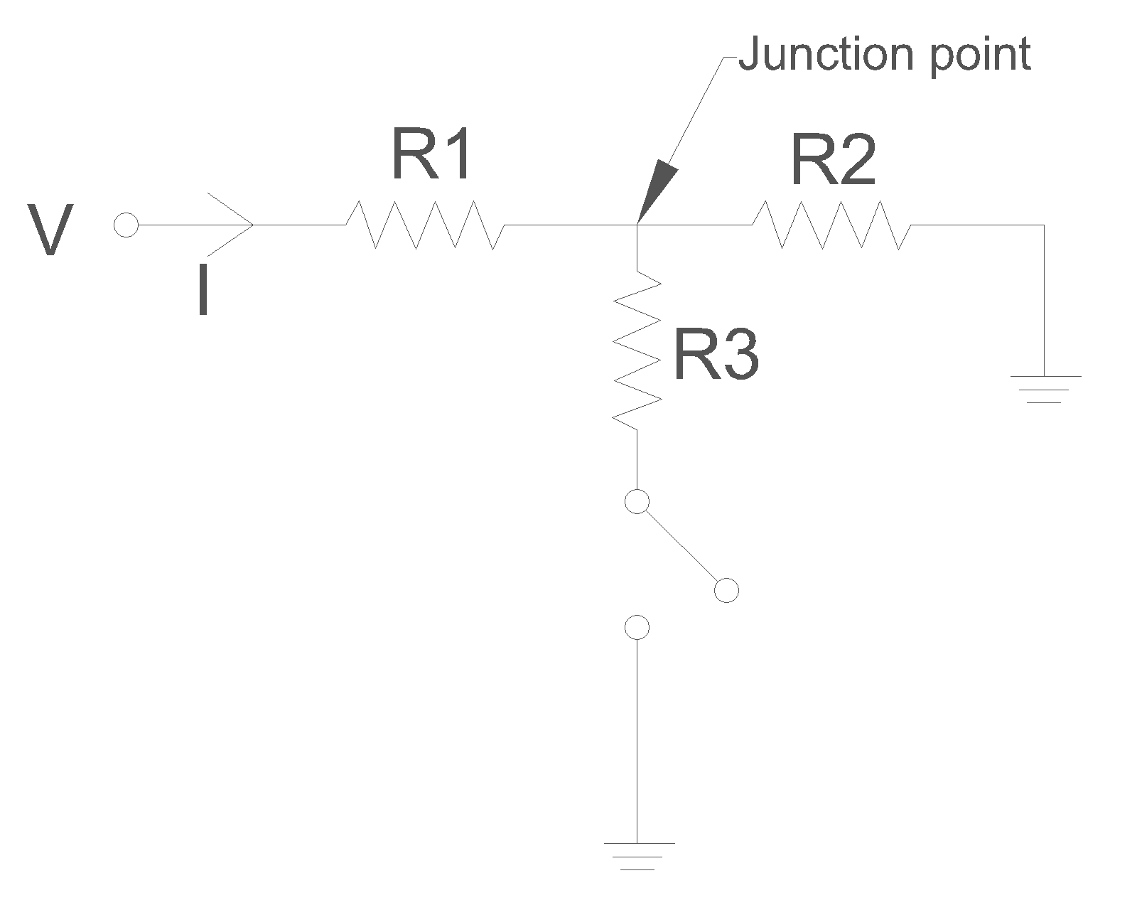
Here voltage $V$ stands for total pressure drop $\Delta p$ that drives the flow; current $I$ stands for total flow rate $Q$; resistance $R$ stand for flow resistances; ground symbol stands for atmospheric pressure (or whatever the pressure is at pipe outlet), which we may take as zero. The junction point between the three resistances is close to where leak occurs. $R1$ represents resistance to flow upstream of the leak, $R2$ represents resistance to flow downstream of the leak, and $R3$ represents resistance to leakage flow. There is a switch between $R3$ and ground. No leakage is equivalent to switch being open. When the switch is closed there is leakage through $R3$.

When there is no leakage, voltage (equivalently, pressure) at junction point is

$V_{junction}=V\frac{R2}{R1+R2}$

When there is leakage

$V_{junction}'=V\frac{\frac{R2~R3}{R2+R3}}{R1+\frac{R2~R3}{R2+R3}}$

Therefore, since $\frac{R2~R3}{R2+R3}<R2$

$\frac{V_{junction}'}{V_{junction}}<1$

What is happening here is that, opening of leakage has reduced total resistance to flow, thus causing an increase in flow rate. Increased flow rate means a larger proportion of the available pressure drop, $\Delta p$, occurs upstream of the leak (across $R1$), thus resulting in less pressure drop across the reduced resistance downstream of the leak. The key here is that leakage results in lowering of resistance to flow, as measured from point of the leak to pipe outlet.

$\endgroup$
6
  • $\begingroup$ So, does the resistance here (based from your explanation) equivalents to Darcy numbers? $\endgroup$ Commented Aug 16, 2016 at 17:03
  • $\begingroup$ Also, can you give real-life examples for the case of constant flow rate? I'd like to compare it with my research limit $\endgroup$ Commented Aug 16, 2016 at 22:36
  • $\begingroup$ I don't know what you mean by Darcy number. Take the Darcy-Weisbach equation and rewrite in the form $\Delta p~\alpha~Q$, with proportionality constant being the resistance (which depends on pipe length over which resistance is being calculated). A piston moving at constant velocity and pushing fluid inside a cylinder results in constant flow rate. For small flow rates, this may be achieved by means of syringe pump. $\endgroup$
    – Deep
    Commented Aug 17, 2016 at 4:43
  • $\begingroup$ what i meant was Darcy fiction factor $\endgroup$ Commented Aug 17, 2016 at 5:57
  • $\begingroup$ i'm stil confused in how you turned the Darcy-Weisbach equation into $\Delta p=RQ$ . The closest that I can find is from Schaum's Fluids Mechanic written in $H_2 - H_1 = RQ^2$ $\endgroup$ Commented Aug 30, 2016 at 16:55

Your Answer

By clicking “Post Your Answer”, you agree to our terms of service and acknowledge you have read our privacy policy.

Not the answer you're looking for? Browse other questions tagged or ask your own question.