2
$\begingroup$

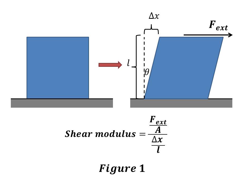
I am a self-learner of continuum mechanic. I am confused about simple shear stress in situation similar to figure 1,

enter image description here

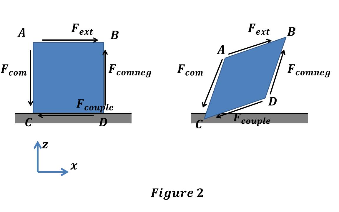
in case $F_\textrm{ext}$ is caused by external perturbation by i.e., human, what are the forces that involve in this scenario? In my mind, there are

  1. $F_\textrm{ext}$ is caused by external perturbation

  2. $F_\textrm{couple}$ which $F_\textrm{couple}=-F_\textrm{ext}$

  3. $F_\textrm{com}$ which are the complementary shear stress multiply with area

  4. $F_\textrm{comneg}$ which $F_\textrm{comneg}=-F_\textrm{com}$ however, these three forces could result in figure 2, not figure 1.

enter image description here

Therefore, I think there should be constraint forces i.e., from human hand, surrounding material or floor that eliminate the force component in $z$ axis by reaction forces.

  1. $F_\textrm{reac}$ which equal to Force components in $z$ axis, $F_\textrm{reac} =-F_\textrm{com}$

Is that right?

in the case of dynamic deformation,it will not necessary that $F_\textrm{couple}$ equal to $-F_\textrm{ext}$ and $F_\textrm{comneg}$ equal to $F_\textrm{com}$. $F_\textrm{reac}$ equal to force components in $z$ axis (in case $F_\textrm{reac}$ is caused from surrounding continuum material) right?

I understand is, in this situation, the object's stiffness reacts to force in x-direction only ($F_\textrm{ext}$ and $F_\textrm{couple}$), not the force in z-direction ($F_\textrm{com}$ and $F_\textrm{comneg}$). Therefore $F_\textrm{reac} =-F_\textrm{com}$. Is this right?

$\endgroup$
2
  • $\begingroup$ $F_{com}$ and $F_{comneg}$ aren't exist because of free edges. $\endgroup$
    – lucas
    Commented May 7, 2016 at 18:55
  • 1
    $\begingroup$ Ok, I get it now. Anyway, does it have Freac normal to surface AB and CD to stop the object from clockwise rotation? $\endgroup$ Commented May 8, 2016 at 9:47

3 Answers 3

0
$\begingroup$

Think of it in this way: If there exists a couple on the center of mass by exerting shear stresses on AB and CD, then shouldn't the block rotate? However, we know from experiment that the block will tend to deform (by a very small amount) as shown in Figure A, so there exists no rotation, which means the system is in rotational equilibrium.

The couple created by the shear stresses is opposed by the couple created by the complementary shear stresses, which prevents turning of the object. The object will not deform to the shape as shown in Figure 2 because $ F_{com} = F_{comneg} $ and is actually a reaction couple to the couple produced by the shear stresses, thus causing deformation in only one direction, which is the direction in which the shear stress was applied.

$\endgroup$
1
  • 1
    $\begingroup$ I still didn't understand why it is not turned out similar to figure 2. If imagine the object as finite group of masses, why isn't a mass at point A goes righty and downward (since the force vectors go that way). Vectors at Point D should move mass at point D toward A. Masses at point B and Point C should move away from each other. I don't think figure 2 is the result of rotation. $\endgroup$ Commented May 8, 2016 at 9:40
0
$\begingroup$

In the small deformation limit figure 1 and 2 are equivalent. Figure 1 is only an intuition driven squematic and should not be used to define the shear stress (or strain) since this is not a pure shear stress state (normal stress is present). In order to properly define the shear stress you should consider a differential surface with shear stresses on its faces. This picture, together with the conservation of linear and angular momentum gives as a result a shear stress of equal magnitude in all faces of the differential element.

$\endgroup$
0
$\begingroup$

You are correct. Your Figure 2 is what a pure shear strain does. Figure 1 is a combination of a shear strain and a rotation.

Strains and rotations of an object are defined by what the matrix M does. They are not defined by some configuration of forces applied to the object, but forces will cause strains and rotations. Strain angles and rotation angles are how we parameterize all the 3x3 matrices that strain and rotate 3-vectors. Rotations and strains form the group GL(3,R). This is the group of all invertible 3x3 matrices M of real numbers.

We can describe what these transformations do by just talking about the matrices $M$ that are very close to the identity matrix, where all elements in the matrix $\Theta$ are <<1. All these elements are in radians. $$ M=I+\Theta $$ $$ \Theta = \begin{bmatrix} 0 & \theta^{12} &-\theta^{13} \\ -\theta^{12} & 0 & \theta^{23} \\ \theta^{13} &-\theta^{23} & 0 \\ \end{bmatrix}_{Asymmetric} \ + \begin{bmatrix} \epsilon^{11} & \epsilon^{12} & \epsilon^{13} \\ \epsilon^{12} & \epsilon^{22} & \epsilon^{23} \\ \epsilon^{13} & \epsilon^{23} & \epsilon^{33} \\ \end{bmatrix}_{Symmetric} $$ The asymmetric elements $\theta$ do rotations. The symmetric elements $\epsilon$ do strains. The symmetric elements on the diagonal do squash strains. The symmetric elements off the diagonal do shear strains.

Your Figure 2 (x,z) plane shear corresponds to only having $\epsilon^{13}\neq 0$. In Figure 2, $\epsilon^{13}$ turns out to be the angle (in radians) between the z and z' edges of the cube and also between the x and x' edges of the cube. You can apply M to vectors to the 4 corners of the cube to verify this is how the cube distorts.

Your Figure 1 needs both $\epsilon^{13}\neq 0$ and $\theta^{13}\neq 0$ so it is a combination of a shear strain and a rotation. You are doing the rotation by pushing the bottom of the block down flat onto the table as you do the shear.

$\endgroup$

Your Answer

By clicking “Post Your Answer”, you agree to our terms of service and acknowledge you have read our privacy policy.

Not the answer you're looking for? Browse other questions tagged or ask your own question.