1
$\begingroup$

I am struggling to frame proper equations for the following two-dimensional mass spring System:

1D Model

Basics first: I started with a simple one-dimensional mass-spring System to model something like a Crash of two rail vehicles:

1D Mass Spring System

The two masses m1 and m2 are the Center of Gravities of the two rail vehicles, while the two springs with their corresponding stiffnesses k1 and k2 model the differences in stiffness of the two colliding wagons. By assuming the mass m3 to be 0, the displacement $S_{M}$ of m3 can be calculated as:

$$ S_{M}=\frac{k_{1}S_{1}+k_{2}S_{2}}{k_{1}+k_{2}} $$

2D Model

Now I was wondering how this model applies to oblique Scenarios and whether we could consider longitudinal and lateral stiffnesses rather than the 1D springs. enter image description here
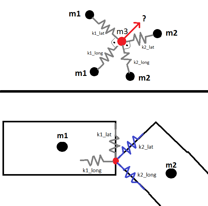
So I split the springs from the 1D model into two springs with separate stiffnesses k1_long, k1_lat, k2_long and k2_lat. The question is now, how the red m3 moves, based on the Forces applied to it through the 4 springs.

My first Approach would have been to decompose the Forces into their x and y components but then I Need to decompose a spring into a x_component spring and a y_component spring, of which I don't know the stiffnesses.

Do you see a possibility to get the movement of m3 (=Connection Point of two wagons) based on the known movements of the other masses and the stiffnesses of the springs?

$\endgroup$
15
  • $\begingroup$ Is this a statics problem, a dynamics problem, or a vibration problem? $\endgroup$ Commented Sep 22, 2015 at 15:50
  • $\begingroup$ It's a dynamic Problem, as the two wagons Keep moving over time $\endgroup$
    – Marcus
    Commented Sep 22, 2015 at 16:00
  • $\begingroup$ So something with zero mass will have infinite acceleration if there is a net force applied to it. So if $m_3$ is small compared to the forces applied you are going to get garbage or unstable results. $\endgroup$ Commented Sep 22, 2015 at 16:03
  • $\begingroup$ So are the two $m_1$ and two $m_2$ masses connected somehow? It is not clear from the diagram at all. Are lat/long always perpendicular or when $m_3$ moves they change the angle between them? $\endgroup$ Commented Sep 22, 2015 at 16:04
  • 1
    $\begingroup$ What you are asking for is not a simple force problem. You would have to model the behavior of the crumpling cars with continuum mechanics. There are programs for that, but it takes years to develop them and the learning curve us very steep. No mass-spring model is going to give you even remotely useful results. $\endgroup$
    – CuriousOne
    Commented Sep 22, 2015 at 19:19

1 Answer 1

0
$\begingroup$

Each side of the contact point has a 2×2 stiffness matrix defined in local (body) coordinates

$$ \begin{align} {\bf k}_1^{\rm body} & = \begin{vmatrix} k_1^{\rm long} & 0 \\ 0 & k_1^{\rm lat} \end{vmatrix} & {\bf k}_2^{\rm body} & = \begin{vmatrix} k_2^{\rm long} & 0 \\ 0 & k_2^{\rm lat} \end{vmatrix} \end{align}$$

Now if each body has a 2×2 orientation (rotation) matrix defined by the angles $\psi_1$ and $\psi_2$ then

$$ \begin{align} {\bf R}_1 &= \begin{vmatrix} \cos\psi_1 & -\sin\psi_1 \\ \sin\psi_1 & \cos\psi_1 \end{vmatrix} & {\bf R}_2 &= \begin{vmatrix} \cos\psi_2 & -\sin\psi_2 \\ \sin\psi_2 & \cos\psi_2 \end{vmatrix} \end{align} $$

The effective 2×2 stiffness (symmetric) matrix in world coordinates is calculated with

$$ {\bf k} = {\bf R}_1 {\bf k}_1^{\rm body} {\bf R}_1^\intercal +{\bf R}_2 {\bf k}_2^{\rm body} {\bf R}_2^\intercal = \begin{vmatrix} k_{xx} & k_{xy} \\ k_{xy} & k_{yy} \end{vmatrix}$$ where $\Box^\intercal$ is the matrix transpose.

What you are looking for is the direction of minimum and maximum stiffness (which are 90°) apart where the contact point would try to move towards. This is found by finding the angle $\varphi$ which causes

$$\begin{vmatrix} \cos\varphi & \sin\varphi \\ -\sin\varphi & \cos\varphi \end{vmatrix} \begin{vmatrix} k_{xx} & k_{xy} \\ k_{xy} & k_{yy} \end{vmatrix} \begin{vmatrix} \cos\varphi & -\sin\varphi \\ \sin\varphi & \cos\varphi \end{vmatrix} = \begin{vmatrix} k_{A} & 0 \\ 0 & k_{B} \end{vmatrix} $$

The solution is $$\varphi = \frac{1}{2} \tan^{-1} \left( \frac{2 k_{xy}}{k_{xx}-k_{yy}} \right ) $$

In addition, every integer $i$ multiple offset $\varphi+i \frac{\pi}{2}$ is also a solution.

$\endgroup$
6
  • $\begingroup$ Hi ja72, thank you very much for this comprehensive answer. I have a few question to go ahead: - I was not aware that the stiffnesses in world cosy can be calculated like shown by you. I wonder why a simple rotation properly splits a given local stiffness into it's world x- and y-components. Furthermore I don't understand why the two sides for k1 and k2 get combined by adding them. To refer to the 1D example - if both, k1 and k2 were 1,then the total stiffness should be 1 and not 1+1=2, shouldn't it? - What do you mean by minimum/maximum stiffness ? - Is $\varphi$ the angle of the movement? $\endgroup$
    – Marcus
    Commented Sep 23, 2015 at 15:21
  • $\begingroup$ The rotation of a stiffness matrix can be interpreted as moving displacements from world coordinates to local coordinates applying the body stiffness and then converting back to world coordinates. Hence the $K = R K_{body} R^\intercal$ transformation. (search congruent transformation) $\endgroup$ Commented Sep 23, 2015 at 20:48
  • $\begingroup$ Stiffness matrices are linear and when expressed in the same coordinates are subject to the principle of superposition (and hence can be added directly). In the 1D case the two springs on the left and right can be added together because they act in the same direction. The stiffness would be 1+1=2 since the force from each spring is felt by $m_3$. The springs are considered "in parallel" actually because they share displacement. $\endgroup$ Commented Sep 23, 2015 at 20:51
  • $\begingroup$ Thank you very much @ja72, you helped me a lot with that problem. Can you please give me a little more explanation on the $k_{A}$ and $k_{B}$ as well as the $\varphi$ - I am not completely sure, whether I got what they are? $\endgroup$
    – Marcus
    Commented Sep 25, 2015 at 12:11
  • $\begingroup$ if $k_A>k_B$ then $\varphi$ is the direction of maximum stiffness and if $k_A<k_B$ it is the direction of minimum stiffness. The values of $k_A$ and $k_B$ are the extrema (minimum maximum) one would feel if pushed along at an oblique angle. When the oblique angle equals $\varphi$ the effective stiffness will be either the minimum possible, or the maximum possible. $\endgroup$ Commented Sep 25, 2015 at 12:50

Your Answer

By clicking “Post Your Answer”, you agree to our terms of service and acknowledge you have read our privacy policy.

Not the answer you're looking for? Browse other questions tagged or ask your own question.