3
$\begingroup$

I have a question about magnetic circuits. I am an engineering student, therefore I will neglect some minor errors.

There is a simple magnetic circuit with 2 coils ($C_1$ & $C_2$), with $N_1$ & $N_2$ turns and $i_1$ & $i_2$ currents. Coils are in series and connected with 1 magnetic core of "O" shape (we may assume some reluctance in form of air gap = $R_c$). The flux linkage of $C_1$ is as follows:

$$ \lambda_1 = N_1 \Phi= N_1 \left(\frac{N_1 i_1}{R_c} + \frac{N_2 i_2}{R_c}\right) $$

so in the end I got something like

$$ \lambda_1=N_1^2i_1\left(\cdots\right)+N_1N_2i_i\left(\cdots\right) $$

The $(\cdots)$ are some constants regarding air gap and core geometry.

I know that magnetic circuit resembles electric circuits. If there would be similar circuit with 2 batteries in series and 1 resistor, the overall voltage would be $V = V_1 + V_2$

In above mentioned magnetic circuit the overall flux linkage would be \begin{align} \lambda_{tot}&=\lambda_1+\lambda_2\\ &=N_1^2i_1\left(\cdots\right)+N_2^2i_2\left(\cdots\right)+2N_1N_2i_2\left(\cdots\right) \end{align}

My questions are then

  1. Why is there the term $2N_1N_2 i_2(...)$ in the last part?
  2. Why is the electric circuit $V = V_1 + V_2$ and no $V_{12}$?
$\endgroup$

2 Answers 2

0
$\begingroup$

I know that magnetic circuit resembles electric circuits.

Yes, but the analogy works between certain specific quantities, and you are considering the wrong ones: the electromotive force does not correspond to the flux linkage, but to the magnetomotive force.

For lumped magnetic and electric circuits, the main correspondences are as follows:

Magnetomotive force $\mathcal{M}$ $\qquad\longleftrightarrow\qquad$ Electromotive force $E$

Magnetic flux $\varPhi$ $\qquad\longleftrightarrow\qquad$ Electric current $I$

Magnetic reluctance $\mathcal{R}$ $\qquad\longleftrightarrow\qquad$ Electric resistance $R$

Only with these correspondences the magnetic analogues of the Kirchhoff's voltage and current laws hold (see also Magnetic circuit on Wikipedia).

In the case of your circuit, the total magnetomotive force is $\mathcal{M} = N_1i_1+N_2i_2 = \mathcal{M}_1+\mathcal{M}_2$, and there isn't any cross-term.

$\endgroup$
0
$\begingroup$

Why is there the term $2N_1N_2i_2$(...) in the last part?

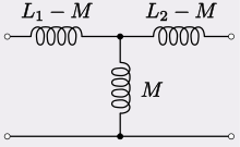
Two coupled inductors are not two two-terminal circuit elements but, rather, one two-port network, e.g.

enter image description here

where

$$M = k\sqrt{L_1L_2} $$

thus, the reason for the $N_1N_2$ terms. Note that as the coupling $k$ goes to zero, we recover the two independent inductors.

$\endgroup$
3
  • $\begingroup$ You say that as $k$ tends to 0 we recover two independent inductors. What then happens with the M attached to the ground rail? $\endgroup$
    – Urgje
    Commented Feb 22, 2015 at 21:11
  • $\begingroup$ @Urgje, M is zero when k is zero, i.e., the middle inductor is a short circuit. However, there is no ground rail in that drawing. $\endgroup$ Commented Feb 23, 2015 at 0:04
  • $\begingroup$ The circuit you posted cannot be used to say that two coupled inductors form a two-port network. In fact, the circuit shown is a circuit which is equivalent to two coupled inductors, but only when the two inductors have, or can have, a terminal in common, and the two-port condition is imposed externally. $\endgroup$ Commented Oct 16, 2016 at 10:30

Your Answer

By clicking “Post Your Answer”, you agree to our terms of service and acknowledge you have read our privacy policy.

Not the answer you're looking for? Browse other questions tagged or ask your own question.