6
$\begingroup$

What is the formula for capacitance of two non parallel plates at an angle with each other?If the plates were parallel then the value can be calculated as (PermittivityX area of one plate)/distance between them.But what happens in case the plates are tilted at an angle?The question came to mind while trying to understand electrostatic separator.What would be the derivation of the formula for capacitance of two non parallel plates placed at an angle?

I did get a method from https://web.archive.org/web/20160417130540/http://www.davidpublishing.com/davidpublishing/upfile/12/15/2011/2011121573197833.pdf Equation 6 from the above link above helps but it is independent of the length of the plates which doesn't seem likely.

$\endgroup$
2
  • $\begingroup$ 13.02.2018: Link now dead. $\endgroup$
    – Qmechanic
    Commented Feb 13, 2018 at 18:28
  • $\begingroup$ 11.05.2021: Link working again. $\endgroup$
    – Poo2uhaha
    Commented May 11, 2021 at 9:26

3 Answers 3

3
$\begingroup$

Let's do some calculus.

Suppose you have two plates, almost parallel (off by an angle $\alpha$). The plates lie in the XY plane, from $(0, 0)$ to $(x_1, y_1)$. At $x = 0$, the plates are separated by a distance $z_0$, and at $x = x_1$, the plates are separated by a distance $z_1$.
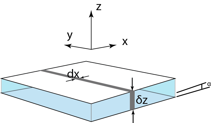
enter image description here

We'll now consider an infinitesimally small element of both plates. (Since parallel capacitances add, and all the infinitesimal pairs are in a parallel configuration, we can use integration)

\begin{align} \tan \alpha &= \frac{z_1 - z_0}{x_1} \\ \mathrm{d}C &= \varepsilon \frac{\mathrm{d}A}{\delta z} \\ \mathrm{d}A &= y_1 ~\mathrm{d}x \\ \delta z &= z_0 + x \tan \alpha \\ \therefore C &= \int\mathrm{d}C \\ &= \int\limits_A \varepsilon \frac{\mathrm{d}A}{\delta z} \\ &= \int\limits_0^{x_1} \varepsilon \frac{y_1 ~\mathrm{d}x}{z_0 + x \tan \alpha} \\ &= \varepsilon ~ y \left[ \cot \alpha \ln(z_0 \cos \alpha + x \sin \alpha) \right]_0^{x_1} \\ &= \varepsilon ~ y_1 \left(\frac{\ln(z_0 \cos \alpha + x_1 \sin \alpha)}{\tan \alpha} - \frac{\ln(z_0 \cos \alpha)}{\tan \alpha} \right) \\ &= \varepsilon ~ y_1 \left( \frac{\ln(1 + (x_1 / z_0) \tan \alpha)}{\tan \alpha} \right) \\ &= \frac{\varepsilon ~ y_1}{\tan \alpha} \ln \left( 1 + \frac{x_1}{z_0} \frac{z_1 - z_0}{x_1} \right) \\ &= \frac{\varepsilon ~ y_1}{\tan \alpha} \ln \left( \frac{z_1}{z_0}\right) \end{align}

If you assume $\alpha$ is small, then $\tan \alpha \approx \alpha$, which gives \begin{align} C &= \frac{\varepsilon ~ y_1}{\alpha} \ln \left(1 + \frac{x_1}{z_0} \right) \end{align}

This conclusion is the same as the Eq. 6 in the paper you linked.

$\endgroup$
1
  • 1
    $\begingroup$ Why should $\delta C = \varepsilon \delta A/\delta z$? This formula only holds if $\delta z$ is small compared to the linear dimension of the plate $\delta A$, which is clearly not the case here. $\endgroup$ Commented Jan 10, 2016 at 9:20
0
$\begingroup$

Assuming that the charge distribution is constant, using the knowledge that capacitance is added in parallel, you could treat your angled plate as being comprised of infinitely many parallel plates, approximating the angle of the plate you would like. You would then be able to integrate across this infinity of plates to find your answer.

As I said, this assumes charge distribution to be even across the plate, and so does not account for fringes. We can say that the charge will be even with a fair amount of certainty due to the knowledge that electric charges in conductors will position themselves to produce equilibrium.

For a more in-depth discussion: https://forum.allaboutcircuits.com/threads/capacitance-of-a-non-parallel-plates.121287/

Sorry for such a short answer!

$\endgroup$
0
$\begingroup$

James Clerk Maxwell himslef identifed the capacitance of a non-parallel plate capacitors in one his "Treatise on Electricity and Magnetism" I believe.

It is possible to determine the capacitance and therefore the "force of electric origin" usign conformal mapping where the non-parallel plate model is transformed to the parallel plate model. In so doing, it is possible to account for the fringing effects in the capacitance and force of electric origin as a function of the gap and the tilt. In the case of the force of electric origin, fringing effects manifest themselves in the accelerometer scale factor.

I did this sort of thing for an electrostatically suspended cubical proof mass accelerometer at Stanford University in the late 70s.

When I discovered that Maxwell solved the problem in his book, I knew I did not need to do any more searching that is for sure.

$\endgroup$

Your Answer

By clicking “Post Your Answer”, you agree to our terms of service and acknowledge you have read our privacy policy.

Not the answer you're looking for? Browse other questions tagged or ask your own question.