3
$\begingroup$

I recently came across a problem in which a 12v DC power supply is connected in parallel to (in one loop) a one microfarad capacitor and a one kilo-ohm resistor. In the other loop is a 1000 microfarad capacitor and a 10 kilo-ohm resistor.

The switch for the supply is turned on for 10 seconds, at which point it is turned off again.

When the switch is turned off we are left with a simple circuit containing two capacitors and two resistors. We are asked to find the initial current in the circuit, and also the voltage across each capacitor once a steady state has been reached. This involves finding both the total resistance and the total capacitance.

In calculating the initial current, the resistances are simply added together as if in series (this is what I would expect).

However, when finding the total capacitance for the voltage calculation I feel there is a somewhat contradiction because the capacitances are simply added together as if in parallel.

How is it that in such a circuit, the resistors are in series, and the capacitors are in parallel? Is this an error in the problem or is there a genuine reason for this?
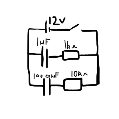
circuit diagram

EDIT: I now understand that the capacitors are in series as they have the same current through them, but if that is the case why can one simply add their capacitances together as though they are in parallel? I am a senior in high school so I'm looking for a reasonably simple answer.

$\endgroup$
5
  • 1
    $\begingroup$ Could you attach a diagram of the circuit? $\endgroup$
    – Kyle Kanos
    Commented Oct 4, 2014 at 12:32
  • $\begingroup$ Well, in some sence the resistors as well as capacitors are both in series and in parallel. $\endgroup$
    – Steeven
    Commented Oct 4, 2014 at 21:03
  • $\begingroup$ which should be used for calculations? $\endgroup$
    – Dylan
    Commented Oct 4, 2014 at 21:30
  • $\begingroup$ Your question can't be answered because the initial conditions at the time the switch is closed are not stated. For example, if both caps are charged to 12 V initially, then nothing will ever happen in this circuit, forever (for ideal parts). $\endgroup$ Commented Oct 6, 2014 at 13:01
  • 1
    $\begingroup$ @OlinLathrop, your observation is strictly true. Practically though, one can answer the question by assuming what almost anyone justifiably assumes without a second thought - that the capacitors are uncharged before the switch is closed. The fact that this isn't explicitly stated in the problem does not change the fact that said assumption is undeniably reasonable and practical. $\endgroup$ Commented Oct 7, 2014 at 0:48

5 Answers 5

5
+25
$\begingroup$

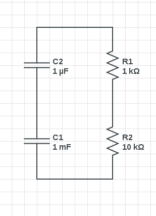
When the switch is opened, the circuit is the equivalent of this, so I think you can clearly see that the resistors are in series and so are the capacitors.

enter image description here

It seems that you already understand how to calculate series resistance, so I'll show how to understand series capacitance. First, you probably already know that capacitance is defined as the ratio of stored charge to voltage. That is, $C=\frac{Q}{V}$. When both of these capacitors are charged, they must have the same charge. That is, $Q_{C1} = Q_{C2}$. Also, the voltages across them must add up to the total voltage, so $V_t = V_{C1} + V_{C2}$. Since we know that $V = \frac{Q}{C}$, we can say $$\begin{eqnarray}V_t &=& V_{C1} + V_{C2} \\ \frac{Q}{C_t} &=& \frac{Q_{C1}}{C1} + \frac{Q_{C2}}{C2} \\ Q\frac{1}{C_t} &=& Q\left(\frac{1}{C1} + \frac{1}{C2}\right)\\ \frac{1}{C_t} &=& \frac{1}{C1} + \frac{1}{C2}\\ C_t &=& \frac{1}{\frac{1}{C1} + \frac{1}{C2}} \end{eqnarray}$$

$\endgroup$
1
  • $\begingroup$ Note that the derivation for the equivalent capacitance assumes that both capacitors are charged and that they have the same charge. This is not the case immediately after your switch is opened, as explained in Girish Pahwa's answer. $\endgroup$
    – Edward
    Commented Oct 6, 2014 at 15:11
1
$\begingroup$

Here the capacitors look like in series but they are not actually. Capacitors can be said to be in series only if they carry same amount of charge which is not the case here.If you calculate charges will come out to be different.Look at the time constants(R*C) for the first branch and second branch, they are 1ms and 10sec respectively. As switch is on initially for 10sec upper capacitor will charge almost fully ($Q=12\mu\text{C}$) while lower branch capacitor will have a charge which is approximately only 63% of the steady state charge (by defination of time constant).You can also use the general result for charging which is $Q=Q_0(1-e^{-t/T})$ where $Q_0$=steady state charge(charge appearing if we would have charged it for a very long time), $T$=time constant, $t$=given time. After calculations you can see charges are different on both the capacitors and hence they can not be considered in series. So you have to go by kirchoff's voltage law for initial current calculation.So first calculate charges after 10sec and then and then voltages across both the capacitors and then apply kirchoff's law for initial current calculation.

$\endgroup$
2
  • $\begingroup$ This is a good point. Although topologically the capacitors are definitely in series, one has to be careful because their initial charges are different and their voltages of opposite polarity. $\endgroup$
    – Edward
    Commented Oct 6, 2014 at 15:09
  • $\begingroup$ I believe the 2nd sentence is incorrect. After the switch is opened, the capacitors are in series since all of the current through one is through the other. This defines series connected circuit elements. I'll elaborate in an answer. $\endgroup$ Commented Oct 6, 2014 at 21:28
1
$\begingroup$

After the switch is opened, we have a series circuit - the current through each circuit element is identical and equal to $i(t)$.

Choosing a clockwise reference direction for the series current, KVL clockwise yields

$$\frac{1}{1\mu F}\int_{-\infty}^t i(\tau) d\tau + i(t) \cdot 1k\Omega + i(t)\cdot10k\Omega + \frac{1}{1000\mu F}\int_{-\infty}^t i(\tau) d\tau = 0$$

Taking the time derivative of both sides and rearranging yields:

$$\left(1k\Omega + 10k\Omega\right)\frac{di(t)}{dt} + \left(\frac{1}{1\mu F}+ \frac{1}{1000\mu F}\right)i(t) = 0$$

or

$$R_{eq}\frac{di(t)}{dt} + \frac{1}{C_{eq}}i(t) = 0$$

As expected, the resistances and capacitances combine as appropriate for series connected circuit elements:

$$R_{eq} = R_1 + R_2 $$

$$C_{eq} = \frac{1}{\frac{1}{C_1} + \frac{1}{C_2}} $$

So, this 'looks like' an ordinary 1st order RC circuit with $R = R_{eq}$ and $C = C_{eq}$.

We are asked to find the initial current in the circuit, and also the voltage across each capacitor once a steady state has been reached.

The initial current is given by

$$i(0) = -\frac{v_{1\mu F}(0) + v_{1000\mu F}(0)}{11k\Omega}$$

but we must be careful to note the sign convention.

Since the reference direction for the series current is clockwise, by the passive sign convention, the left-most terminal of the $1\mu F$ capacitor is considered positive while the right-most terminal of the $1000 \mu F$ capacitor is considered positive.

In other words, we expect that

$$v_{1\mu F}(0) > 0 $$

$$v_{1000\mu F}(0) < 0 $$

Since it is stipulated that the switch is closed for 10 seconds before opening at $t=0$, we can calculate the initial voltages

$$v_{1\mu F}(0) = 12V\left(1 - e^{\frac{10}{1\mu f \cdot 1k\Omega}} \right) $$

$$v_{1000\mu F}(0) = 12V\left(1 - e^{\frac{10}{1000\mu f \cdot 10k\Omega}} \right) $$

and thus, the initial current.

In steady state, the series current is zero which means that the capacitor voltages add to zero, i.e., are equal and opposite.

$\endgroup$
0
$\begingroup$

The best way to go about these kind of problems, is to use Kirchoff's loops.

Whenever there is ambiguity about parallel/serial, Kirchoff is the way, since you disregard the question of serial vs. parallel altogether.

Also remember that while resistors observe: $$ \frac{1}{R_T}=\frac{1}{R_1}+\frac{1}{R_2} $$ for parallel and, $$ R_T=R_1+R_2 $$ for serial, The opposite is true for capacitors!

$\endgroup$
0
$\begingroup$

When the current is turned on for 10 seconds the capacitors have gradually charged according to the equation Q(t)=CV(1-e^(-RC)) Now after 10 seconds when the switch is open the two capacitors act as two voltage sources in parallel and the current could be found out by superposition principle which is used when we have more than one source

$\endgroup$

Your Answer

By clicking “Post Your Answer”, you agree to our terms of service and acknowledge you have read our privacy policy.

Not the answer you're looking for? Browse other questions tagged or ask your own question.