3
$\begingroup$

I tried to post this question on Computational Science SE, but I was really unsure about the most appropriate SE site. The question didn't attract a lot of attention, and since Physics SE was my second-best guess, I try again here. I have slightly modified the question, in order to make it in-topic for this site.

Consider a semicylinder of radius $R$ with a round top, i.e., an axisymmetric solid which extends to infinity in one direction along its axis, and has a round head in the other direction. Something like this Rankine solid. The semicylinder is vertical, and at the junction between the round top and the remaining semicylinder ($z=0$) there is a slit (or a collection of small holes along the circumferential direction, but I think the slit would be easier to model), through which liquid with a very low velocity $V_g$ exits and falls around the semicylinder, under the effect of gravity. Around the cylinder, gas flows in the negative $z$ direction, with velocity $V_l$, thus pushing the film towards $z=-\infty$. At the same time, the semicylinder is heated from inside. The heat flow rate is not very large, but the liquid film should be very thin ($V_l $ is small, and $V_g$ is large), so I guess there may be increased evaporation from the film.

I need to dimension the system so that a thin film of liquid is generated around the cylinder. For example, I can imagine that I should make $V_l$ quite small, otherwise I would get a fountain, and not a liquid film around the cylinder. In particular, I need to estimate the liquid film thickness $h$. To start, heating may be neglected, but I would like to at least have an idea of how the film thickness would be affected by heating. I guess the estimate will be a function of $R$, $V_l$, $V_g$, as well as liquid and gas viscosities and densities.

Probably $h$ will also be a function of $z$. Intuitively, film acceleration due to gravity will tend to reduce the film thickness (by conservation of mass). On the other hand, I think friction between gas and liquid will tend to bring the liquid speed to that of the gas, and stop accelerating. So maybe there is an asymptotic thickness.

Can you help me?

EDIT: I haven't specified parameter values, because I'd rather have an expression of $h$ as a function of $\rho_g, \rho_l, R,\dots$, than just a number would like a generic answer, and also because the setup hasn't been frozen, thus I could make it bigger/smaller/increase flow rates/reduce them/etc. if that is needed to get a thin film. Anyway, just to put the problem in context, I give reference values for a couple parameters, but I want to stress that they are not definitive, and they can be modified if you believe that to be necessary in order to get a liquid film. $R\approx 5\,cm$, $V_g\approx 50 \,m \cdot s^{-1} $, gas is CO2 and liquid is water with dissolved CO2.

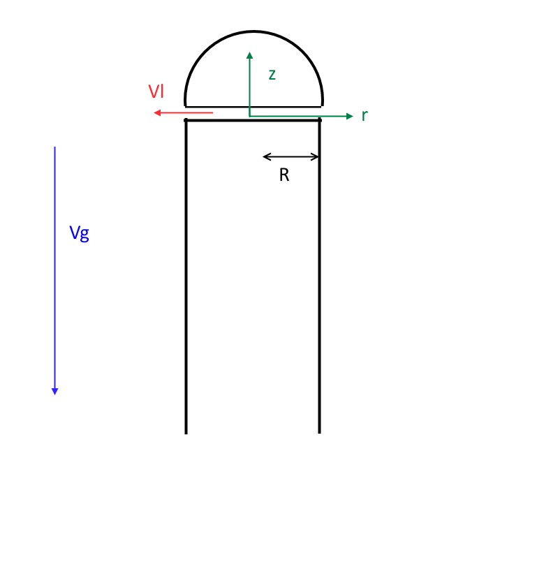
EDIT: added a "nifty" sketch to clarify the setup enter image description here

$\endgroup$
8
  • $\begingroup$ I might be able to help, but I'm having difficulty picturing the scenario. A diagram of the scenario you are describing would be very helpful. $\endgroup$ Commented May 30, 2016 at 17:24
  • $\begingroup$ Ok! Cannot draw right now but I'll be home in about an hour and I will make a picture. Thanks for your interest in the question! $\endgroup$
    – DeltaIV
    Commented May 30, 2016 at 17:32
  • $\begingroup$ You need to provide material properties and approximate dimensions. The outcome will depend on the surface tension and the contact angle between the liquid and the surface. With water on a typical surface, you won't get a film, but at best a layer of a few mm thick and a velocity that is likely higher than "very low". $\endgroup$ Commented May 30, 2016 at 18:12
  • $\begingroup$ @NauticalMile, added a sketch, hope it's more clear now. $\endgroup$
    – DeltaIV
    Commented May 31, 2016 at 12:10
  • $\begingroup$ @Han-KwangNienhuys, the setup hasn't been frozen. I could change dimensions and materials if needed. I could even change geometry and orientation, if that's really needed (for example, go to an horizontal, 2D setup, instead than the actual axisymmetric, vertical setup), though I would only do that if it's extremely difficult to get what I want with the current setup. Can you assume generic values for the parameters, and write $h$ as a function of those parameters? This way, I could compare different setups (speed, flow rate, radius, etc.) in terms of the corresponding $h$. $\endgroup$
    – DeltaIV
    Commented May 31, 2016 at 12:16

1 Answer 1

3
$\begingroup$

What you're asking is actually a quite complicated engineering problem. You are not telling what you're really trying to achieve (is it a heat exchanger? Cooling system? Piece of art? Gas humidifier?), so it is very well possible that your proposed system is not the optimal solution. Anyway, your question which can be broken down into a number of sub-problems:

  1. The liquid must slide down as a uniform film.
  2. The nozzle for supplying the liquid must not spray.
  3. In the presence of a given heat flux, the film must not evaporate completely (you imply this without stating so explicitly).

Parameters that you can choose are: liquid flow rate, cylinder diameter, nozzle shape, cylinder material, gas flow surrounding the cylinder. Parameters that you cannot choose are: liquid properties (carbonated water), heat flux.

This cannot be solved for a true semi-infinite cylinder, since somewhere down, all liquid will have evaporated. Moreover, requirement #1 is extremely difficult if the liquid flows over a long distance.

Problem #1 (uniform film). You need to use a cylinder material that has an extremely high wettability (low contact angle). Online text books and Wikipedia will tell you that clean metals and glass have a high wettability. However, if you take a clean stainless-steel knife straight from the dishwasher and run tap water over it, you'll see the water forming channels if the flow rate is low (tap at dripping speed). Channeling is probably unavoidable for your infinite cylinder; for a finite cylinder, it may be avoided. Adding grooves/ribs to the cylinder or wrapping the cylinder in cotton fabric or a sponge cloth may help here. Adding a surfactant (dishwashing liquid or rinse aid) to the liquid could also help. It's not clear whether those are acceptable for what you want to do with it.

Another problem with keeping the film uniform is that a high-speed gas flow may cause ripples in the film surface, in particular if the film is thick (more than a mm or so).

Problem #2 (no spray) the way you draw it, with the outflow vector perpendicular to the cylinder axis and a sharp edge, makes this difficult to avoid. Try to make the nozzle aim downward and round the corner (it's much easier to pour from a thin-walled vessel than from a thick-walled mug with a rounded edge; here you want the opposite).

Problem #3 (evaporation) this is a difficult topic; if you consider it to be an engineering problem, you will have to state more requirements (do you need evaporation or can you do without? How much heat flux?)

Assuming that you somehow manage to design the system for film flow, then the physics exercise of mathematically describing the flow becomes manageable.

See picture below for the geometry and expected velocity profile.

Cylinder flow geometry If you want the gas drag to help the liquid to flow downward, you have to specify a boundary condition on the gas; hence the outer shell.

The indices are 1 for liquid and 2 for gas properties. Other parameters:

  • $u_2\approx 10^2~\mathrm{m/s}$ - average gas velocity
  • $u_1$ - liquid velocity at the interface with the gas
  • $\mu_1=10^{-3}~\mathrm{Pa\,s}, \mu_2=10^{-5}~\mathrm{Pa\,s}$ - viscosities
  • $\rho=10^3~\mathrm{kg/m^3}$ - liquid density
  • $g=10~\mathrm{m/s^2}$ - gravity
  • $Q$ - liquid flow rate per unit of width, in $\mathrm{m^2/s}$
  • $h, H$ - thicknesses of the liquid and the gas layers.

First, estimate whether the flow is likely to be driven by gravity or by viscous drag. The shear stress in the gas at the interface with the liquid is approximately $4u_2\mu_2/H$, assuming laminar flow. The shear stress due to gravity will be about $\rho g h/2$. If I plug in some numbers, e.g. $h=10^{-3}$ m and $H=10^{-2}$ m, then it appears that the effect of gravity is about 10x larger than the effect of viscous drag.

For a film of thickness $h$ sliding along a surface due to gravity, one can derive that the velocity profile will be $$ v(z) = \frac{\rho g}{2\mu_1}(2hz - z^2) $$ This can be derived analogously to how you would derive Poiseuille's law. The flow rate would then be $$ Q = \int_0^h v(z) dz = \frac{\rho g h^3}{3\mu_1}. $$ I cannot tell you the minimum film thickness that will be stable against channeling, but my gut feeling after watching water run down a knife is that you need to set $h>0.5~\mathrm{mm}$, which will result in a mean film speed $Q/h=0.8$ m/s.

The above is all with the assumption of laminar flow. For the proposed values of the gas speed $u_2$, that is unlikely (Reynolds number $\sim 10^5$), which means a high risk of ripple formation and much more gas drag than in the laminar-flow approximation. If you want to have a more thorough analysis, including turbulence, heat transfer, and evaporation, you'll have to hire me...

$\endgroup$

Your Answer

By clicking “Post Your Answer”, you agree to our terms of service and acknowledge you have read our privacy policy.

Not the answer you're looking for? Browse other questions tagged or ask your own question.