added 249 characters in body
Source Link
Alex Trounev
  • 3.8k
  • 1
  • 14
  • 22

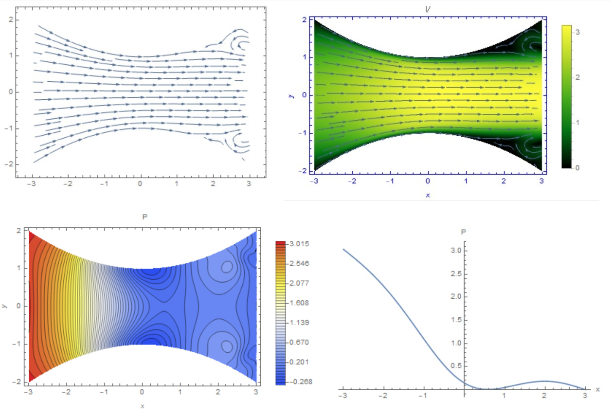
In the case of viscous flow, I gave the answer here. Viscous laminar flow during expansion of the nozzle will come off the walls with the formation of a jet and return flow zones - see Figure 1. Figure 1
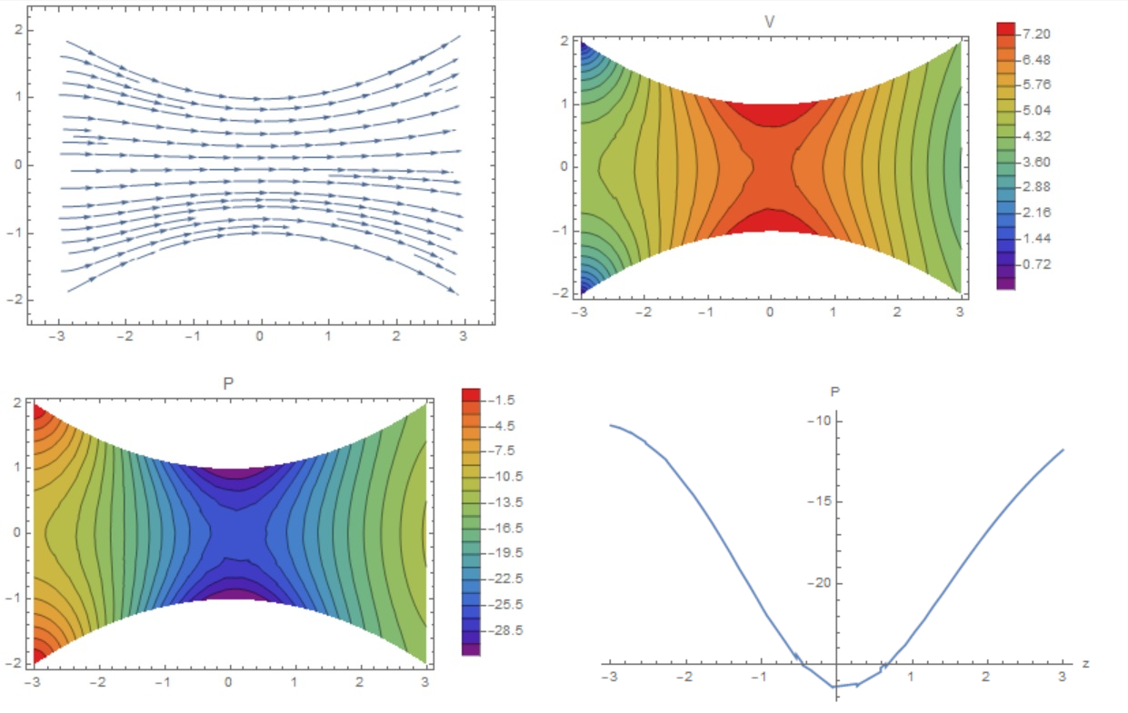
In the case of an inviscid continuous flow, the distribution of velocity and pressure is shown in Fig.2. In this case, the pressure distribution on the axles is similar to what @Drew drew. In both cases, a parabolic velocity profile is specified at the input. fig1
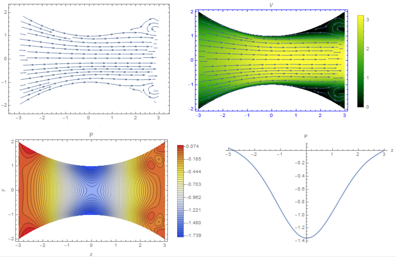
Align the pressure in the viscous flow at the inlet and outlet of the pipe by subtracting $\rho gz$. The distribution of the velocity of the flow does not change, and the distribution of pressure on the axis takes the form similar to that painted @Drew. Figure 3
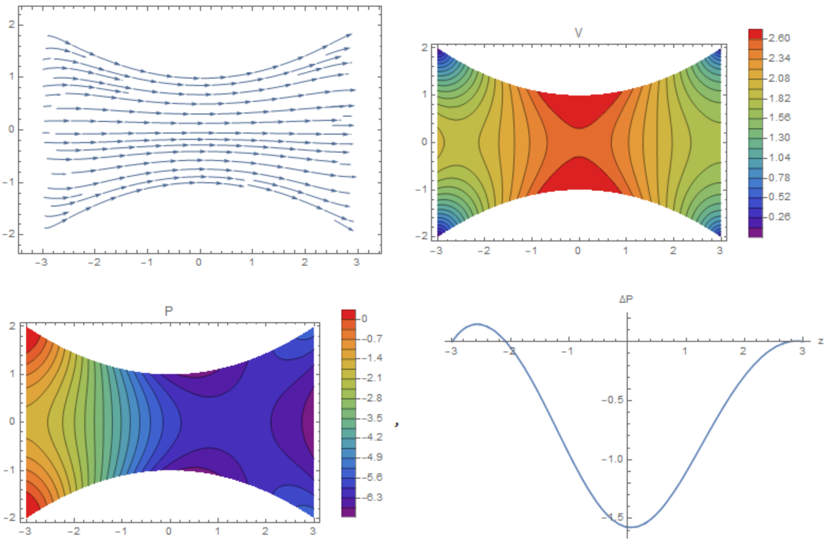
Now we need to calibrate the two solutions so that we can coordinate the pressure on the axis. First, we can calibrate by the water flow rate at the pipe inlet by setting the same velocity profile. Such inviscid flow is shown in Fig.4, where $\Delta P=P-\rho gz$. Figure 4
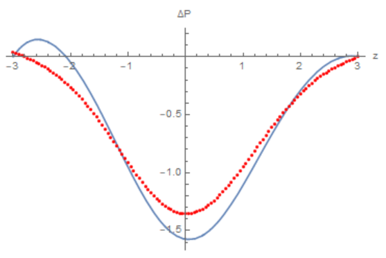
Finally, it is possible to compare two pressure profiles on the axis for viscous (red) and inviscid flow (blue) with the same velocity profile at the inlet to the pipe - Figure 5. Figure 5
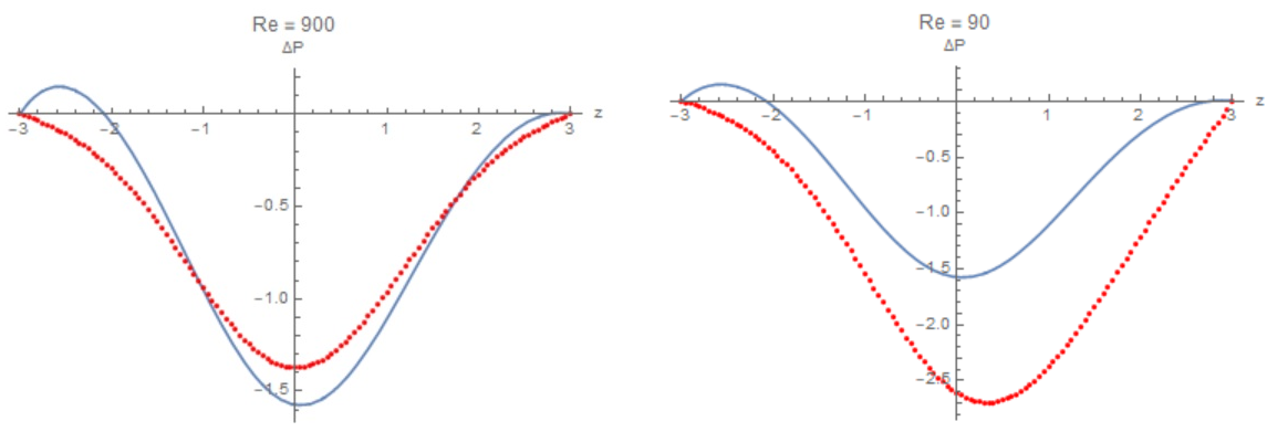
However, if we reduce the Reynolds number to $Re=90$ and create a non-separable flow, then the pressure distribution will be similar to what @Drew suggested - see Figure 6 (right). Figure 6
In the case of viscous flow, I gave the answer here. Viscous laminar flow during expansion of the nozzle will come off the walls with the formation of a jet and return flow zones - see Figure 1. Figure 1

In the case of an inviscid continuous flow, the distribution of velocity and pressure is shown in Fig.2. In this case, the pressure distribution on the axles is similar to what @Drew drew. In both cases, a parabolic velocity profile is specified at the input. fig1

Align the pressure in the viscous flow at the inlet and outlet of the pipe by subtracting $\rho gz$. The distribution of the velocity of the flow does not change, and the distribution of pressure on the axis takes the form similar to that painted @Drew. Figure 3

Now we need to calibrate the two solutions so that we can coordinate the pressure on the axis. First, we can calibrate by the water flow rate at the pipe inlet by setting the same velocity profile. Such inviscid flow is shown in Fig.4, where $\Delta P=P-\rho gz$. Figure 4

Finally, it is possible to compare two pressure profiles on the axis for viscous (red) and inviscid flow (blue) with the same velocity profile at the inlet to the pipe - Figure 5. Figure 5

However, if we reduce the Reynolds number to $Re=90$ and create a non-separable flow, then the pressure distribution will be similar to what @Drew suggested - see Figure 6 (right). Figure 6

Bounty Ended with 200 reputation awarded by Thermodynamix
added 486 characters in body
Source Link
Alex Trounev
  • 3.8k
  • 1
  • 14
  • 22

In the case of viscous flow, I gave the answer here. Viscous laminar flow during expansion of the nozzle will come off the walls with the formation of a jet and return flow zones - see Figure 1. Figure 1

In the case of an inviscid continuous flow, the distribution of velocity and pressure is shown in Fig.2. In this case, the pressure distribution on the axles is similar to what @Drew drew. In both cases, a parabolic velocity profile is specified at the input. fig1

Align the pressure in the viscous flow at the inlet and outlet of the pipe by subtracting $\rho gz$. The distribution of the velocity of the flow does not change, and the distribution of pressure on the axis takes the form similar to that painted @Drew. Figure 3

Now we need to calibrate the two solutions so that we can coordinate the pressure on the axis. First, we can calibrate by the water flow rate at the pipe inlet by setting the same velocity profile. Such inviscid flow is shown in Fig.4, where $\Delta P=P-\rho gz$. Figure 3Figure 4

Finally, it is possible to compare two pressure profiles on the axis for viscous (red) and inviscid flow (blue) with the same velocity profile at the inlet to the pipe - Figure 5. Figure 5

In the case of viscous flow, I gave the answer here. Viscous laminar flow during expansion of the nozzle will come off the walls with the formation of a jet and return flow zones - see Figure 1. Figure 1

In the case of an inviscid continuous flow, the distribution of velocity and pressure is shown in Fig.2. In this case, the pressure distribution on the axles is similar to what @Drew drew. In both cases, a parabolic velocity profile is specified at the input. fig1

Align the pressure in the viscous flow at the inlet and outlet of the pipe by subtracting $\rho gz$. The distribution of the velocity of the flow does not change, and the distribution of pressure on the axis takes the form similar to that painted @Drew. Now we need to calibrate the two solutions so that we can coordinate the pressure on the axis. Figure 3

In the case of viscous flow, I gave the answer here. Viscous laminar flow during expansion of the nozzle will come off the walls with the formation of a jet and return flow zones - see Figure 1. Figure 1

In the case of an inviscid continuous flow, the distribution of velocity and pressure is shown in Fig.2. In this case, the pressure distribution on the axles is similar to what @Drew drew. In both cases, a parabolic velocity profile is specified at the input. fig1

Align the pressure in the viscous flow at the inlet and outlet of the pipe by subtracting $\rho gz$. The distribution of the velocity of the flow does not change, and the distribution of pressure on the axis takes the form similar to that painted @Drew. Figure 3

Now we need to calibrate the two solutions so that we can coordinate the pressure on the axis. First, we can calibrate by the water flow rate at the pipe inlet by setting the same velocity profile. Such inviscid flow is shown in Fig.4, where $\Delta P=P-\rho gz$. Figure 4

Finally, it is possible to compare two pressure profiles on the axis for viscous (red) and inviscid flow (blue) with the same velocity profile at the inlet to the pipe - Figure 5. Figure 5

added 418 characters in body
Source Link
Alex Trounev
  • 3.8k
  • 1
  • 14
  • 22

In the case of viscous flow, I gave the answer here. Viscous laminar flow during expansion of the nozzle will come off the walls with the formation of a jet and return flow zones - see Figure 1. Figure 1

In the case of an inviscid continuous flow, the distribution of velocity and pressure is shown in Fig.2. In this case, the pressure distribution on the axles is similar to what @Drew drew. In both cases, a parabolic velocity profile is specified at the input. fig1

Align the pressure in the viscous flow at the inlet and outlet of the pipe by subtracting $\rho gz$. The distribution of the velocity of the flow does not change, and the distribution of pressure on the axis takes the form similar to that painted @Drew. Now we need to calibrate the two solutions so that we can coordinate the pressure on the axis. Figure 3

In the case of viscous flow, I gave the answer here. Viscous laminar flow during expansion of the nozzle will come off the walls with the formation of a jet and return flow zones - see Figure 1. Figure 1

In the case of an inviscid continuous flow, the distribution of velocity and pressure is shown in Fig.2. In this case, the pressure distribution on the axles is similar to what @Drew drew. In both cases, a parabolic velocity profile is specified at the input. fig1

Align the pressure in the viscous flow at the inlet and outlet of the pipe by subtracting $\rho gz$. The distribution of the velocity of the flow does not change, and the distribution of pressure on the axis takes the form similar to that painted @Drew. Now we need to calibrate the two solutions so that we can coordinate the pressure on the axis. Figure 3

Source Link
Alex Trounev
  • 3.8k
  • 1
  • 14
  • 22
Loading