added 5 characters in body
Source Link
Philip Wood
  • 36.6k
  • 3
  • 35
  • 85

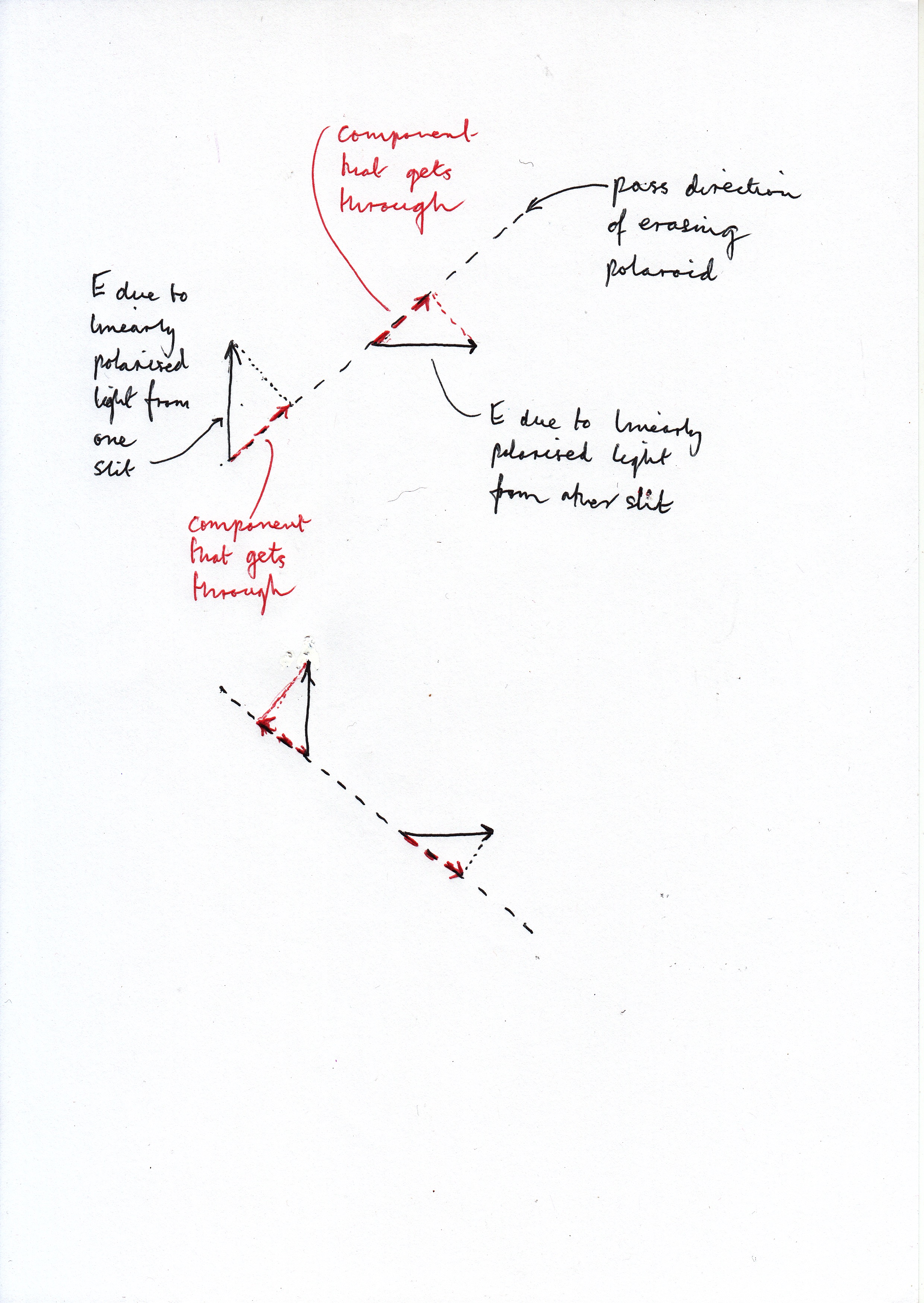
The diagrams represent light coming out of the screen towards us. There are therefore oscillating electric and magnetic fields in the plane of the screen. We don't need to consider the magnetic field, so I've left it out. I'm assuming (to make things easy) that linearly polarised light from one slit has an electric field increasing in the upward direction while light from the other has an electric field increasing to the right. Hence the black arrows. [Soon the upward and right-ward fields will reduce and then become downwards and leftwards respectively, and so on. In other words the fields are oscillating.]

Polaroid filters let through only the electric field components oscillating only in one directionalignment. As you can see from the diagrams, the components of these fields that get through the analyser (eraser) polaroid will be in phase with each other when this polaroid is at +45°, but in anti phase when it is at –45°. The diagram shows the electric fields at a particular time, but these phase relationships continue to be true at other times.

So an extra half wavelength (or half a wavelength less) of path difference will be needed to give the same sort of fringe (bright say). Therefore there will be dark fringes where there were bright fringes previously, and vice versa.

enter image description here

The diagrams represent light coming out of the screen towards us. There are therefore oscillating electric and magnetic fields in the plane of the screen. We don't need to consider the magnetic field, so I've left it out. I'm assuming (to make things easy) that linearly polarised light from one slit has an electric field increasing in the upward direction while light from the other has an electric field increasing to the right. Hence the black arrows. [Soon the upward and right-ward fields will reduce and then become downwards and leftwards respectively, and so on. In other words the fields are oscillating.]

Polaroid filters let through only the electric field components oscillating in one direction. As you can see from the diagrams, the components of these fields that get through the analyser (eraser) polaroid will be in phase with each other when this polaroid is at +45°, but in anti phase when it is at –45°. The diagram shows the electric fields at a particular time, but these phase relationships continue to be true at other times.

So an extra half wavelength (or half a wavelength less) of path difference will be needed to give the same sort of fringe (bright say). Therefore there will be dark fringes where there were bright fringes previously, and vice versa.

enter image description here

The diagrams represent light coming out of the screen towards us. There are therefore oscillating electric and magnetic fields in the plane of the screen. We don't need to consider the magnetic field, so I've left it out. I'm assuming (to make things easy) that linearly polarised light from one slit has an electric field increasing in the upward direction while light from the other has an electric field increasing to the right. Hence the black arrows. [Soon the upward and right-ward fields will reduce and then become downwards and leftwards respectively, and so on. In other words the fields are oscillating.]

Polaroid filters let through only the electric field components oscillating only in one alignment. As you can see from the diagrams, the components of these fields that get through the analyser (eraser) polaroid will be in phase with each other when this polaroid is at +45°, but in anti phase when it is at –45°. The diagram shows the electric fields at a particular time, but these phase relationships continue to be true at other times.

So an extra half wavelength (or half a wavelength less) of path difference will be needed to give the same sort of fringe (bright say). Therefore there will be dark fringes where there were bright fringes previously, and vice versa.

enter image description here

added 291 characters in body
Source Link
Philip Wood
  • 36.6k
  • 3
  • 35
  • 85

The diagrams represent light coming out of the screen towards us. There are therefore oscillating electric and magnetic fields in the plane of the screen. We don't need to consider the magnetic field, so I've left it out. I'm assuming (to make things easy) that linearly polarised light from one slit has an electric field increasing in the upward direction while light from the other has an electric field increasing to the right. Hence the black arrows. [Soon the upward and right-ward fields will reduce and then become downwards and leftwards respectively, and so on – if you see what I mean. In other words the fields are oscillating.]

ThenPolaroid filters let through only the electric field components oscillating in one direction. As you can see from the diagrams, the components of these fields that get through the analyser (eraser) polaroid will be in phase with each other when this polaroid is at +45°, but in anti phase when it is at –45°. SeeThe diagram – which shows the electric fields at somea particular time, for example when they are bothbut these phase relationships continue to be true at a maximumother times.

So an extra half wavelength (or half a wavelength less) of path difference will be needed to give the same sort of fringe (bright say). Therefore there will be dark fringes where there were bright fringes previously, and vice versa.

enter image description here

The diagrams represent light coming out of the screen towards us. There are therefore oscillating electric and magnetic fields in the plane of the screen. We don't need to consider the magnetic field, so I've left it out. I'm assuming (to make things easy) that linearly polarised light from one slit has an electric field increasing in the upward direction while light from the other has an electric field increasing to the right and so on – if you see what I mean.

Then the components of these fields that get through the analyser polaroid will be in phase with each other when this polaroid is at +45°, but in anti phase when it is at –45°. See diagram – which shows the electric fields at some particular time, for example when they are both at a maximum.

So an extra half wavelength (or half a wavelength less) of path difference will be needed to give the same sort of fringe (bright say). Therefore there will be dark fringes where there were bright fringes previously, and vice versa.

enter image description here

The diagrams represent light coming out of the screen towards us. There are therefore oscillating electric and magnetic fields in the plane of the screen. We don't need to consider the magnetic field, so I've left it out. I'm assuming (to make things easy) that linearly polarised light from one slit has an electric field increasing in the upward direction while light from the other has an electric field increasing to the right. Hence the black arrows. [Soon the upward and right-ward fields will reduce and then become downwards and leftwards respectively, and so on. In other words the fields are oscillating.]

Polaroid filters let through only the electric field components oscillating in one direction. As you can see from the diagrams, the components of these fields that get through the analyser (eraser) polaroid will be in phase with each other when this polaroid is at +45°, but in anti phase when it is at –45°. The diagram shows the electric fields at a particular time, but these phase relationships continue to be true at other times.

So an extra half wavelength (or half a wavelength less) of path difference will be needed to give the same sort of fringe (bright say). Therefore there will be dark fringes where there were bright fringes previously, and vice versa.

enter image description here

added 262 characters in body
Source Link
Philip Wood
  • 36.6k
  • 3
  • 35
  • 85

The diagrams represent light coming out of the screen towards us. There are therefore oscillating electric and magnetic fields in the plane of the screen. We don't need to consider the magnetic field, so I've left it out. I'm assuming (to make things easy) that linearly polarised light from the two slits has one slit has an electric field increasing upwardsin the upward direction while light from the other ishas an electric field increasing to the right and so on – if you see what I mean.

Then the components of these fields that get through the analyser polaroid will be in phase with each other when this polaroid is at +45°, but in anti phase when it is at –45°. See diagram – which shows the electric fields at some particular time, for example when they are both at a maximum.

So an extra half wavelength (or half a wavelength less) of path difference will be needed to give the same sort of fringe (bright say). Therefore there will be dark fringes where there were bright fringes previously, and vice versa.

enter image description here

I'm assuming (to make things easy) that linearly polarised light from the two slits has one electric field increasing upwards while the other is increasing to the right and so on – if you see what I mean.

Then the components of these fields that get through the analyser polaroid will be in phase with each other when this polaroid is at +45°, but in anti phase when it is at –45°. See diagram – which shows the electric fields at some particular time, for example when they are both at a maximum.

So an extra half wavelength (or half a wavelength less) of path difference will be needed to give the same sort of fringe (bright say). Therefore there will be dark fringes where there were bright fringes previously, and vice versa.

enter image description here

The diagrams represent light coming out of the screen towards us. There are therefore oscillating electric and magnetic fields in the plane of the screen. We don't need to consider the magnetic field, so I've left it out. I'm assuming (to make things easy) that linearly polarised light from one slit has an electric field increasing in the upward direction while light from the other has an electric field increasing to the right and so on – if you see what I mean.

Then the components of these fields that get through the analyser polaroid will be in phase with each other when this polaroid is at +45°, but in anti phase when it is at –45°. See diagram – which shows the electric fields at some particular time, for example when they are both at a maximum.

So an extra half wavelength (or half a wavelength less) of path difference will be needed to give the same sort of fringe (bright say). Therefore there will be dark fringes where there were bright fringes previously, and vice versa.

enter image description here

added 103 characters in body
Source Link
Philip Wood
  • 36.6k
  • 3
  • 35
  • 85
Loading
deleted 4 characters in body
Source Link
Philip Wood
  • 36.6k
  • 3
  • 35
  • 85
Loading
Source Link
Philip Wood
  • 36.6k
  • 3
  • 35
  • 85
Loading