added 453 characters in body
Source Link

I'm currently studying induction law and circuits with inductors. I came however with the following circuit:

enter image description here

Now my text says the following:

"Unlike what your intuition might tell you, oscilloscopes 1 and 2 will measure different voltages. For a N-turn coil you will get

$$u' = N\frac{d\phi}{dt}$$ $$u'' = (N-1)\frac{d\phi}{dt}$$ "

How is that possible? I'm having trouble on understanding why this results are obtained. I understand (I think) that the oscilloscopes will measure different values because the induction E field is non conservative. But I don't understand their computation. How does the left side sees one coil less than the right side?

EDIT: Some additional information: At bold we have a ferromagnetic core that is excited by a sinusoidal current flowing in an inductor (not shown) which gives rise to a magnetic flux in the core. A N-turn coil is wound around the core. The coil is left open (i=0), but due to induction phenomena a voltage u(t) appears across its terminals a and b. In order to visualize the coil voltage, two oscilloscopes O1 and O2 are connected between a and b.

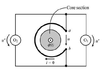
I'm currently studying induction law and circuits with inductors. I came however with the following circuit:

enter image description here

Now my text says the following:

"Unlike what your intuition might tell you, oscilloscopes 1 and 2 will measure different voltages. For a N-turn coil you will get

$$u' = N\frac{d\phi}{dt}$$ $$u'' = (N-1)\frac{d\phi}{dt}$$ "

How is that possible? I'm having trouble on understanding why this results are obtained. I understand (I think) that the oscilloscopes will measure different values because the induction E field is non conservative. But I don't understand their computation. How does the left side sees one coil less than the right side?

EDIT: Some additional information: At bold we have a ferromagnetic core that is excited by a sinusoidal current flowing in an inductor (not shown) which gives rise to a magnetic flux in the core. A N-turn coil is wound around the core. The coil is left open (i=0), but due to induction phenomena a voltage u(t) appears across its terminals a and b. In order to visualize the coil voltage, two oscilloscopes O1 and O2 are connected between a and b.

Source Link

How is it possible that the two voltmeters in parallel measure these different voltages

I'm currently studying induction law and circuits with inductors. I came however with the following circuit:

enter image description here

Now my text says the following:

"Unlike what your intuition might tell you, oscilloscopes 1 and 2 will measure different voltages. For a N-turn coil you will get

$$u' = N\frac{d\phi}{dt}$$ $$u'' = (N-1)\frac{d\phi}{dt}$$ "

How is that possible? I'm having trouble on understanding why this results are obtained. I understand (I think) that the oscilloscopes will measure different values because the induction E field is non conservative. But I don't understand their computation. How does the left side sees one coil less than the right side?