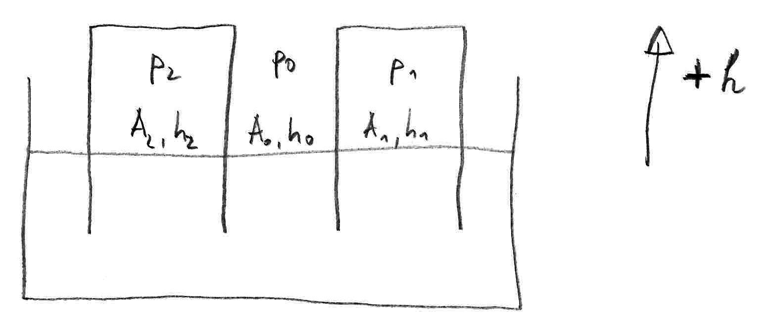
Let's define: $A$ is the water surface area, $h$ is the water height above mean level (positive values pointing upward), $p$ is the pressure at the water surface, index $0$ is the ambient part, indices $1$ and $2$ are the two tanks. So $A_0$ is the water surface area of the sump, $h_1$ is the water height in tank 1 and $p_2$ is the pressure at the water surface of tank 2. This is depicted by the following sketch.
Water movement
Assuming the water is incompressible, the volume changes $\Delta V_i = A_i \, h_i$ must level out (the continuity equation): $$ \Delta V_0 + \Delta V_1 + \Delta V_2 = 0 \quad\Leftrightarrow\quad A_0 \, h_0 + A_1 \, h_1 + A_2 \, h_2 = 0 \quad\mbox{.} $$ Assuming the water surface areas of tanks and the sump are constant (all have vertical walls), the surface velocities are $$ v_i = \frac{\mathrm{d}h_i}{\mathrm{d}t} \quad\mbox{.} $$ Now let's apply Bernoulli's equation (the instationary one) between surfaces $1$ and $0$: $$ \tfrac12 v_0^2 + g\,h_0 + \frac{p_0}\rho = \int_0^1 \frac{\partial v}{\partial t} \,\mathrm{d}s + \tfrac12 v_1^2 + g\,h_1 + \frac{p_1}\rho \quad\mbox{.} $$ The same can be done between surfaces $2$ and $0$. With known state $h_i$, $v_i$, $p_i$, this allows to calculate the integrals $\int \partial v / \partial t \,\,\mathrm{d}s$.
The overall topicdifficult part is calledderiving the $\partial v_i / \partial t$ from those integrals, because the acceleration along the whole streamline is integrated. For the streamline part above the level where the tank walls end, the velocity can be considered constant. If the part below that level is neglected in the first place, the integral can be expressed as $$ \int_0^1 \frac{\partial v}{\partial t} \,\mathrm{d}s = -\frac{\mathrm{d}v_0}{\mathrm{d}t} (h_0-h) + \frac{\mathrm{d}v_1}{\mathrm{d}t} (h_1-h) $$ with the (negative) height of the tank walls (negative value since its below the mean water level). The different signs in front of $\frac{\mathrm{d}v_0}{\mathrm{d}t}$ and $\frac{\mathrm{d}v_1}{\mathrm{d}t}$ are because the integral path is from position $0$ to position $1$, and positive velocities are upward.
Together with the continuity equation, we have the following three equations: $$ A_0 \, h_0 + A_1 \, h_1 + A_2 \, h_2 = 0 \\ \tfrac12 \left( \frac{\mathrm{d}h_0}{\mathrm{d}t} \right)^2 + g\,h_0 + \frac{p_0}\rho + \frac{\mathrm{d}^2 h_0}{\mathrm{d}t^2} (h_0-h) = \frac{\mathrm{d}^2 h_1}{\mathrm{d}t^2} (h_1-h) + \tfrac12 \left( \frac{\mathrm{d}h_1}{\mathrm{d}t} \right)^2 + g\,h_1 + \frac{p_1}\rho \\ \tfrac12 \left( \frac{\mathrm{d}h_0}{\mathrm{d}t} \right)^2 + g\,h_0 + \frac{p_0}\rho + \frac{\mathrm{d}^2 h_0}{\mathrm{d}t^2} (h_0-h) = \frac{\mathrm{d}^2 h_2}{\mathrm{d}t^2} (h_2-h) + \tfrac12 \left( \frac{\mathrm{d}h_2}{\mathrm{d}t} \right)^2 + g\,h_2 + \frac{p_2}\rho $$ After integrating the continuity equation into the other two, we have two coupled second order differential equations for (e.g.) $h_1$ and $h_2$ with initial values for $h_1$, $h_2$, $v_1$ and $v_2$ that remain to be solved.
Air flow and air pressure
Similar considerations are required for the air flow. The major difference is that air is compressible. One idea would be to take the air mass inside the tanks (above the water surface) as state variable and create a model for that. Sorry, but I don't have the time for that now.
Dissipating effects
So far, this neglects dissipating effects like flow velocity profiles. Also, the pressure at the water surface remains to be solved. For all this, pipe flow could be utilized. Also the effect of the water streaming from the tanks into the sump (the water flow below the end of the tank walls) could be included as an additional pressure loss using this theory.
In generalpipe flow, the pressure loss $\Delta p/\rho$ ($\rho$ = fluid density) is calculated for each element, and then Bernoulli's equation is used to calculate the flow velocity $v$ or volumetric flow rate $\dot V = v \cdot A$ ($A$ = cross section area).
Applying Bernoulli's equation between the surfaces of the two cylinders yieldsEffectively, considering dissipating effects reduces the available pressure difference $$ \frac{\Delta p}{\rho}=g\cdot (z_2-z_1)=g\cdot \Delta z $$ with Earth gravitydifferences between $g$$0$ and surface heights $z_1$$1$ and between $z_2$$0$ and $2$.
Putting it all together yields a formula that allows you to calculate $v$ as a function of $\Delta z$.Conclusions
To sum up, this is quite complicated. I'm sorry I don't have the resources to solve this, you need a kinematic equation coupling $\Delta z$ with. An approach would be the volume $V$, flow velocity $v$ and cross section area $A$Euler method (or pipe diametera $D$Runge-Kutta method if you prefer higher order).
Finally, you shouldcould check if the assumption of laminar flow is appropriate or not. Generally, laminar flow is considered for $Re < 2300$ and turbulent flow for $Re > 5000$. In between those two values, the flow regime depends on pipe roughness and the turbulence at the inlet (in your case probably none).
PS: If this is a homework type question it should be tagged as such.

